Contents

Interfacing TB6600 Stepper Motor Driver with Arduino

Discover the amazing capabilities of the TB6600 stepper motor driver when paired with an Arduino. This comprehensive guide will walk you through the process of interfacing these two powerful components. By following this guide, you’ll be able to adjust microsteps, understand pinouts, and even explore code examples.

TB6600 Stepper Motor Driver Features

The TB6600 is an easy-to-use professional stepper motor driver that you can adjust its microsteps. This module could control a two-phase stepping motor. A key feature of this module is that you can change the microstep settings by the built-in switches on the driver.

These modules have several safety functions as follows:

  • Overcurrent protection
  • under-voltage shutdown
  • overheating protection

There are 2 kinds of this module: 4 Amps and 4.5 Amps. Both have similar functions. You can see these modules in the image below.

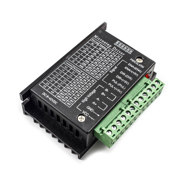
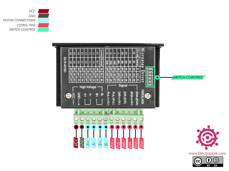
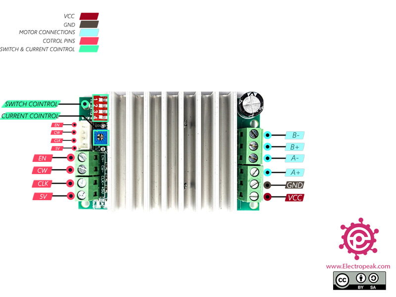
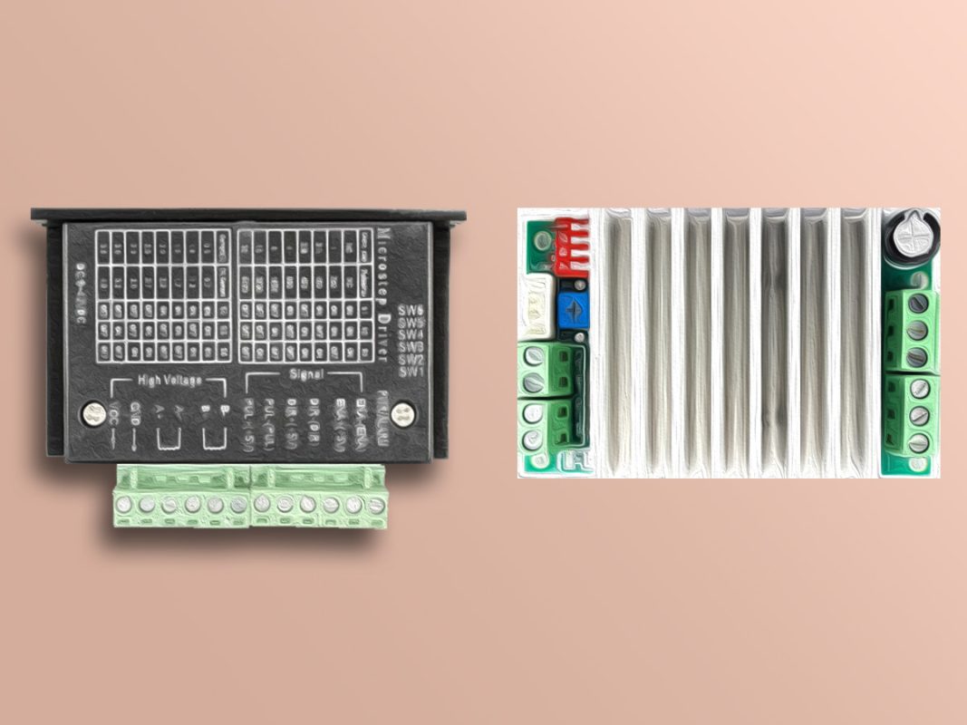
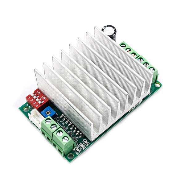
You can download the datasheet of this module here.

TB6600 Stepper Motor Driver Pinout

This Module has the following pins:

High Voltage  

  • VCC: Motor power supply – 9-42V for 4A type and max 32V for 4.5A type
  • GND: Ground
  • A+: Positive pin of coil 1
  • A-: Negative pin of coil 1
  • B+: Positive pin of coil 2
  • B-: Negative pin of coil 2

Signal  

  • PUL(CLK): Pins for controlling rotation steps
  • DIR(CW): Pins for controlling rotation steps
  • ENA: Enable the driver pin
  • 5V: Voltage – 5V
Note

There are 2 way that you can command the PUL, DIR and ENA pins in 4A type:

  1. Connect The negative pins to ground and do the control by positive pins. (Active -HIGH)
  2.  Connect the positive pins to 5 volts and do the control by negative pins. (Active -LOW)
Note

For the 4.5A type, the other pins are activated with LOW voltage because there is a 5V pin in the control pins.

TB6600 stepper motor driver control switches

These switches are used to control the microstep resolution and limiting the driver current.

You can change the microstep resolution from full step to 1/32 step by switching the switches S1 to S3.

Note

There is no 1/32 step in 4.5A type.

You can adjust the current that goes to the motor when it is running by setting the dip switches S4, S5, and S6 on or off.

Note

In 4.5A type, you can adjust and limit the current by the potentiometer.

You can see the pinout of this module in the image below.

Required Material

Required Material

Arduino UNO R3 × 1
TB6600 4A Stepper Motor Driver × 1
TB6600 4.5A Stepper Motor Driver × 1
BYGH403 1.65A Stepper Motor × 1
Male to Male Jumper Wire × 1

Software Apps

Arduino IDE
Note

Use a power supply with a proper current and voltage to power the motor.

Note

For this tutorial, prepare only one type of TB6600.

Interfacing TB6600 Stepper Motor Driver with Arduino

To begin interfacing the TB6600 stepper motor driver with an Arduino, follow these steps:

Step 1: Circuit

Note

You can use a multimeter to find the two wires from one coil.
Place the multimeter on short circuit test and test the wires in pairs. The two wires that were short circuited while connecting to the multimeter are both sides of one coil.

The following circuit show how you should connect Arduino and stepper motor to 4A type. Connect wires accordingly.

Note

You can limit the current with the dip switches according to power supply that you have chosen.

Note

In this tutorial, we set switches 3 and 6 to Off. Therefore, the driver will be in full step mode and the continuous current is 1.5A.

Note

We have connected the negative side of control pins to ground and controlled these pins by commanding to the positive side. (Active-High)

The 4.5A type is also connected to other parts as shown below:

Step 2: Code

Upload the following code to Arduino.

 /*
  TB6600-Stepper-Motor-Driver
  made on 15 Dec 2020
  by Amir Mohammad Shojaee @ Electropeak
  
Home
*/ #define dirPin 8 #define stepPin 9 void setup() { // Declare pins as output: pinMode(stepPin, OUTPUT); pinMode(dirPin, OUTPUT); // Set the spinning direction CW/CCW: digitalWrite(dirPin, HIGH); } void loop() { // These four lines result in 1 step: digitalWrite(stepPin, HIGH); delayMicroseconds(500); digitalWrite(stepPin, LOW); delayMicroseconds(500); }

Connect pin 8 to DIR (CW) and pin 9 to PUL (CLK). Set DIR pin to High. The rotation direction of the stepper motor is clockwise in 4A type and counter-clockwise in 4.5A type. The motor then rotates by creating a square pulse with the step pin.

Next, we want to change the step manually by the driver switches. For example, first we set pin S1 and then S2 to off. By doing this, the driver step in 4A type, first becomes 1/8 and then 1/32. Finally, by increasing the step, the motor speed decreases and its resolution increases. In the 4.5A type, the driver step first becomes 1/8 and then stops because it doesn’t have a 1/32 step.


By following these steps and understanding the code, you’ll be able to effectively interface the TB6600 stepper motor driver with your Arduino and harness its full potential.

Now you are ready to embark on an exciting journey of controlling stepper motors using the powerful TB6600 driver in conjunction with your Arduino. Enjoy exploring the endless possibilities of precise motor control and automation!

Liked What You See?​
Get Updates And Learn From The Best​

Leave a Reply

Your email address will not be published. Required fields are marked *