Interfacing SS49E Linear Hall Effect Sensor Module with Arduino
Written by
Mehran Maleki
SS49E Linear Hall Effect Sensor Features
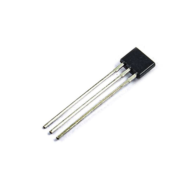
The output of SS49E linear Hall sensor provides an analog voltage representing if a magnetic field is present. So, this small and versatile sensor can be used in systems containing permanent magnets or an electromagnets in order to monitor magnetic field change. The output voltage is in the range of 2.25V to 2.75V. In this sensor, amplifier, voltage regulator and logic switching circuits are used to overcome noise in the output.
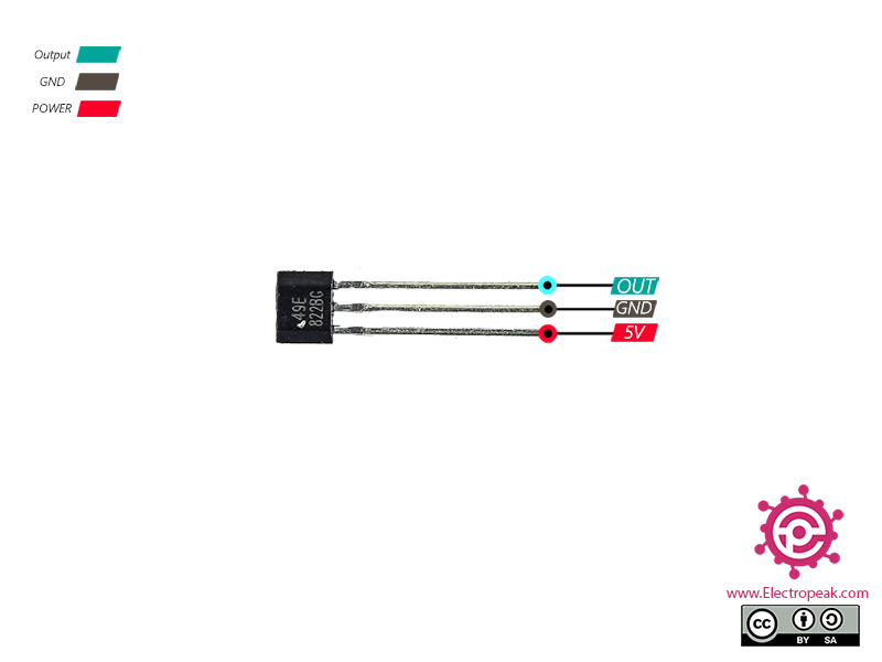
SS49E Linear Hall Effect Sensor Pinout
This Module has 3 pins:
OUT: Analog Output
GND: Ground
VCC: Module power supply – 5V
You can see the pinout of this module in the image below.
Required Material
Hardware component
Arduino UNO R3
×
1
SS49E Linear Hall Effect Sensor
×
1
Male to Female jumper wire
×
1
Software Apps
Arduino IDE
Interfacing SS49E Linear Hall Effect Sensor with Arduino
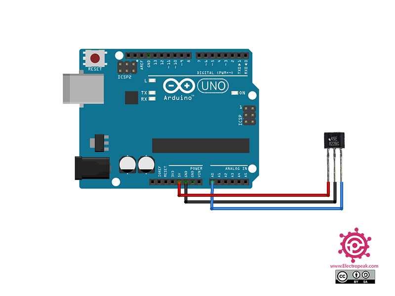
Step 1: Circuit
The following circuit show how you should connect Arduino to SS49E sensor. Connect wires accordingly.
Step 2: Code
Upload the following code to your Arduino. After that open Serial Plotter.
/*
Made on Dec 19, 2020
By MehranMaleki @ Electropeak
In the above code, we used Arduino pin A0 for receiving analog output data. Then we observe the sonsor performance by placing a magnet in front of module and removing it. (changing the magnetic field surrounding the sensor)