PCF8591 AD/DA Features
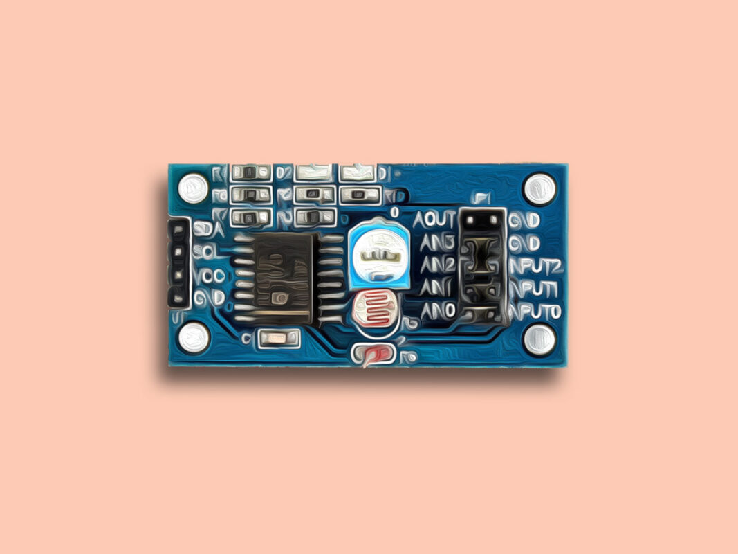
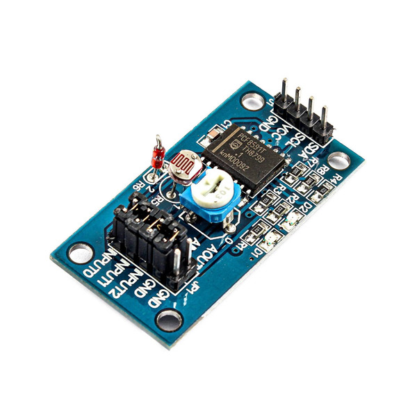
The PCF8591 is a single-chip, single-supply low power 8-bit CMOS data acquisition device. This chip has four analog inputs, one analog output, and a serial I2C-bus interface.
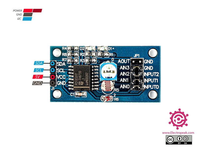
The PCF8591 module has 4 pins on the left, which include the power pins and the I2C connection pins. The 8 right pins with 4 jumpers on them also work with signals:
- AOUT: Module DAC output interface
- AINO: chip analog input interface
- AIN1: chip analog input interface
- AIN2: chip analog input interface
- AIN3: chip analog input interface
- INPUT2: Signal input port that thermistor is connected to it
- INPUT1: Signal input port that photoresistor is connected to it
- INPUT0: Signal input port that potentiometer is connected to it
You can download the datasheet of this module here.
PCF8591 Module Pinout
This sensor has 4 pins:
- VIN: Module power supply – 5 V
- GND: Ground
- SLC: I2C clock
- SDA: I2C data
You can see the pinout of this module in the image bellow.
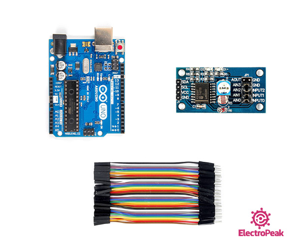
Required Materials
Hardware Components
Software Apps
Interfacing PCF8591 Module with Arduino
Step 1: Circuit
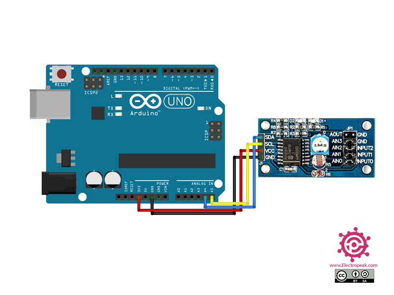
The following circuit shows how you should connect Arduino to PCF8591 module. Connect wires accordingly.
Step 2: Code
Install the following library on your Arduino first.
Tip
If you need more help with installing a library on Arduino, read this tutorial: How to Install an Arduino Library
Upload the following code to your Arduino.
/*
  modified on Sep 23, 2020
  Modified by MohammedDamirchi from https://github.com/adafruit/Adafruit_PCF8591
  Home
*/


#include <Adafruit_PCF8591.h>
// Make sure that this is set to the value in volts of VCC
#define ADC_REFERENCE_VOLTAGE 5.0
Adafruit_PCF8591 pcf = Adafruit_PCF8591();

void setup() {
  Serial.begin(115200);
  while (!Serial)
    delay(10);

  Serial.println("# Adafruit PCF8591 demo");
  if (!pcf.begin()) {
    Serial.println("# Adafruit PCF8591 not found!");
    while (1)
      delay(10);
  }
  Serial.println("# Adafruit PCF8591 found");
  pcf.enableDAC(true);


}

uint8_t dac_counter = 0;

void loop() {
  // Make a triangle wave on the DAC output
  pcf.analogWrite(dac_counter);
  dac_counter = dac_counter + 10;
  Serial.print("AIN0: ");
  Serial.print(int_to_volts(pcf.analogRead(0), 8, ADC_REFERENCE_VOLTAGE));
  Serial.print("\t AIN1: ");
  Serial.print(int_to_volts(pcf.analogRead(1), 8, ADC_REFERENCE_VOLTAGE));
  Serial.print("\t AIN2: ");
  Serial.print(int_to_volts(pcf.analogRead(2), 8, ADC_REFERENCE_VOLTAGE));
  Serial.print("\t AIN3: ");
  Serial.print(int_to_volts(pcf.analogRead(3), 8, ADC_REFERENCE_VOLTAGE));

  Serial.println("");
  delay(3);
}
float int_to_volts(uint16_t dac_value, uint8_t bits, float logic_level) {
  return (((float)dac_value / ((1 << bits) - 1)) * logic_level);
}
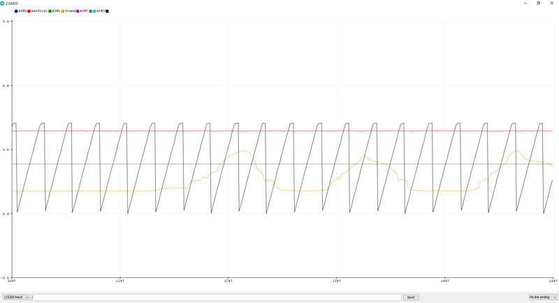
After running the code, you will see the following image in the serial monitor.
