Contents

Interfacing NEO-7M GPS Module with Arduino

NEO-7M GPS Module Features

GY-NEO-7M module is an advanced GPS module that supports UART communication protocol with active antenna. You can interface this module easily with any microcontroller. This module has a rechargeable battery and can also be connected directly to a computer using a USB to TTL converter.

This module can receive data and then calculate the geographical position with a very high accuracy and speed. In addition to supporting BeiDou, Galileo, GLONASS, GPS / QZSS, the module has internal memory to save settings. This module is compatible with Arduino and can be used in any project.

Tip

The on-board LED starts blinking when module is connecting to GPS satellites.

You can download the datasheet of this module here.

NEO-7M GPS Module Pinout

This sensor has 4 pins:

  • VIN: Module power supply – 5 V
  • GND: Ground
  • RX: Receive data via serial protocol
  • TX: Sending data via serial protocol

You can see pinout of this module in the image below.

Required Materials

Hardware Components

Arduino UNO R3 × 1
NEO-7M GPS Module × 1
Male to Female jumper wire × 1

Software Apps

Arduino IDE

Interfacing NEO-7M GPS Module with Arduino

Step 1: Circuit

The following circuit shows how you should connect Arduino to NEO-7M module. Connect wires accordingly.

Step 2: Code

Install the following library on your Arduino.

https://github.com/mikalhart/TinyGPSPlus

Tip

If you need more help with installing a library on Arduino, read this tutorial: How to Install an Arduino Library

Upload the following code to your Arduino.

    /*   
modified on Sep 27, 2020
Modified by MohammedDamirchi from https://github.com/mikalhart/TinyGPSPlus
Home
*/ #include <TinyGPS++.h> #include <SoftwareSerial.h> /* This sample sketch demonstrates the normal use of a TinyGPS++ (TinyGPSPlus) object. It requires the use of SoftwareSerial, and assumes that you have a 9600-baud serial GPS device hooked up on pins 4(rx) and 3(tx). */ static const int RXPin = 3, TXPin = 4; static const uint32_t GPSBaud = 9600; // The TinyGPS++ object TinyGPSPlus gps; // The serial connection to the GPS device SoftwareSerial ss(RXPin, TXPin); void setup() { Serial.begin(115200); ss.begin(GPSBaud); Serial.println(F("DeviceExample.ino")); Serial.println(F("A simple demonstration of TinyGPS++ with an attached GPS module")); Serial.print(F("Testing TinyGPS++ library v. ")); Serial.println(TinyGPSPlus::libraryVersion()); Serial.println(F("by Mikal Hart")); Serial.println(); } void loop() { // This sketch displays information every time a new sentence is correctly encoded. while (ss.available() > 0) if (gps.encode(ss.read())) displayInfo(); if (millis() > 5000 && gps.charsProcessed() < 10) { Serial.println(F("No GPS detected: check wiring.")); while(true); } } void displayInfo() { Serial.print(F("Location: ")); if (gps.location.isValid()) { Serial.print(gps.location.lat(), 6); Serial.print(F(",")); Serial.print(gps.location.lng(), 6); } else { Serial.print(F("INVALID")); } Serial.print(F(" Date/Time: ")); if (gps.date.isValid()) { Serial.print(gps.date.month()); Serial.print(F("/")); Serial.print(gps.date.day()); Serial.print(F("/")); Serial.print(gps.date.year()); } else { Serial.print(F("INVALID")); } Serial.print(F(" ")); if (gps.time.isValid()) { if (gps.time.hour() < 10) Serial.print(F("0")); Serial.print(gps.time.hour()); Serial.print(F(":")); if (gps.time.minute() < 10) Serial.print(F("0")); Serial.print(gps.time.minute()); Serial.print(F(":")); if (gps.time.second() < 10) Serial.print(F("0")); Serial.print(gps.time.second()); Serial.print(F(".")); if (gps.time.centisecond() < 10) Serial.print(F("0")); Serial.print(gps.time.centisecond()); } else { Serial.print(F("INVALID")); } Serial.println(); }

After uploading the code, you can see the output in the serial monitor.

Liked What You See?​
Get Updates And Learn From The Best​

Comments (10)

  • Fabian Kreitschir Reply

    Hi
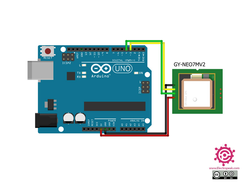
    I just wanted to try out your code for my school project. But every time i try to get a signal, it alsways answers with “No GPS detected: please check wiring”. I know what it means and everything is connected properly. I think the problem is the antenna, but could there possibly be anything else wrong.

    March 16, 2022 at 1:13 pm
    • Mehran Maleki Reply

      Hi,
      Well, this is as use said most likely because of the antenna. But, there is also another thing you can check. Try the project outdoors. Actually, the NEO-7M GPS module works best when used in the open air. Also, wait for around 5 to 10 minutes after you power up the module since it usually takes a few minutes to connect to the GPS network.

      March 19, 2022 at 8:17 pm
    • ve6wcr Reply

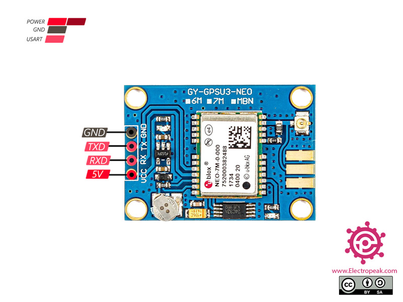
      the rx and tx pins are reversed in the diagram

      August 11, 2022 at 3:17 am
      • Mehran Maleki Reply

        Well, you seem to be correct! Thanks for your attention.
        The problem is now solved by modifying line 14 of the code and changing the pin numbers assigned to Rx and Tx.

        August 12, 2022 at 1:36 pm
  • thomas Reply

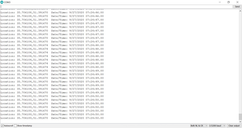
    Hi The only thing I get back from the monitor is: $M&/�Ht�\Xn;�EVp��g�

    Any ideas. GPS is blinking, jumers are oke.

    December 30, 2022 at 4:01 pm
    • Ali Abdolmaleki Reply

      Hi
      check your serial baudrate please
      it should be 115200

      March 1, 2023 at 6:41 am
  • Peter Reply

    How can i set it to 10Hz mode?

    May 31, 2023 at 9:07 pm
    • Mohammad Damirchi Reply

      hi peter
      Normally, the library doesn’t support the “update rate mode.”
      Before library configuration, you can adjust the “update rate mode” by the
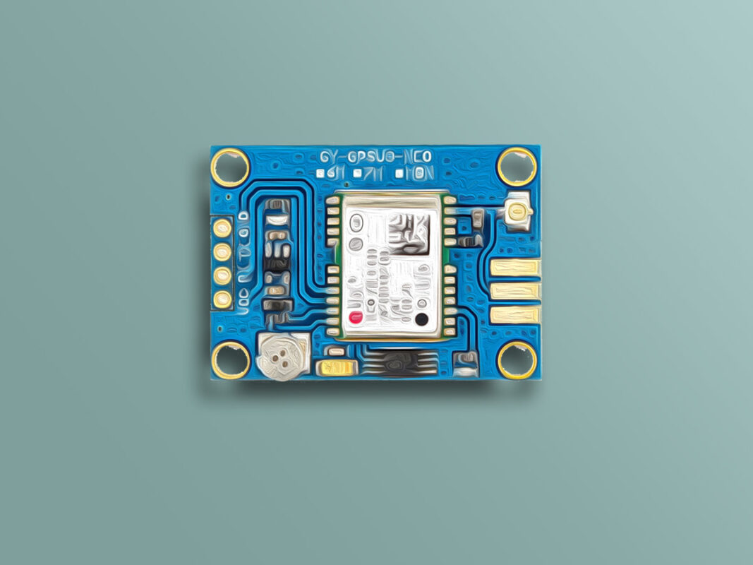
 GSMSerial.println("$PMTK220,100") command

      June 3, 2023 at 7:13 am
  • Smurfy Reply

    The ublox NEO 6,7,8 GPS modules are 3.3v devices. They should NOT be powered directly from the arduino 5v supply. Use the 3.3v output instead !!!!!

    March 5, 2024 at 8:47 pm
    • Mohammad Damirchi Reply

      Hi Smurfy,
      Thank you for your notice. If you examine the PCB for these models, you’ll notice they incorporate an LDO regulator to stabilize the voltage at 3.3 volts for the IC.

      March 9, 2024 at 8:41 am

Leave a Reply

Your email address will not be published. Required fields are marked *