MT8870 DTMF Decoder Module Features
DTMF stands for Dual-tone-multi-frequency. This module is for sending signals using the voice-frequency band over telephone lines to switching centers. This module has two important applications: First, to specify the desired number to telecommunication through switching centers; second, it is capable of transmitting commands to these centers and other telecommunication devices.
Technical specifications:
- Input voltage: 5V
- 5mm input jack
- LED to indicate the binary outputs status
- Recognize numbers 0-9, letters A-D and symbols *, #
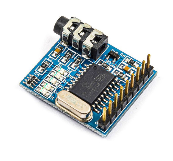
MT8870 DTMF Decoder Module Pinout
This module has 6 pins:
- VCC: Module power supply
- GND: Ground
- Q[1-4]: Binary Output
- EST: Early Steering (Output)
- INH: Inhibit (Input)
- TOE: Three State Output Enable (Input)
You can see the pinout of this module here.

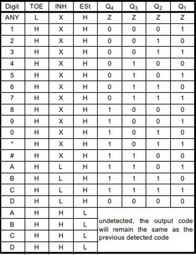
Different modes in each pin represent different data. The following table shows different modes:
Required Materials
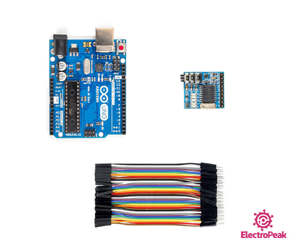
Hardware Components
Software Apps
Note
You need an AUX cable to interface this module.
Interfacing MT8870 DTMF Decoder Module with Arduino
Step 1: Circuit
The following circuit shows how you should connect MT8870 module to Arduino and to the mobile phone using the AUX cable. Connect wires accordingly.

Step 2: Code
Upload the following code to your Arduino.
   /*
MT8870-DTMF-Receiver-Module
Made on 09 Feb, 2021
Home

*/

void setup() {
  Serial.begin(9600);
  pinMode(3, INPUT);
  pinMode(4, INPUT);
  pinMode(5, INPUT);
  pinMode(6, INPUT);
  pinMode(7, INPUT);
}

void loop() {
  uint8_t number;
  bool signal;
  signal = digitalRead(7);
  if (signal == HIGH)     /*When DTMF tone is detected, STQ will read HIGH for the duration of the tone*/
  {
    delay(100);
    number = ( 0x00 | (digitalRead(3) << 0) | (digitalRead(4) << 1) | (digitalRead(5) << 2) | (digitalRead(6) << 3) );
    switch (number)
    {
      case 0x01:
        Serial.println("Pin Pressed: 1");
        break;
      case 0x02:
        Serial.println("Pin Pressed: 2");
        break;
      case 0x03:
        Serial.println("Pin Pressed: 3");
        break;
      case 0x04:
        Serial.println("Pin Pressed: 4");
        break;
      case 0x05:
        Serial.println("Pin Pressed: 5");
        break;
      case 0x06:
        Serial.println("Pin Pressed: 6");
        break;
      case 7:
        Serial.println("Pin Pressed: 7");
        break;
      case 0x08:
        Serial.println("Pin Pressed: 8");
        break;
      case 0x09:
        Serial.println("Pin Pressed: 9");
        break;
      case 0x0A:
        Serial.println("Pin Pressed: 0");
        break;
      case 0x0B:
        Serial.println("Pin Pressed: *");
        break;
      case 0x0C:
        Serial.println("Pin Pressed: #");
        break;
    }
  }
}
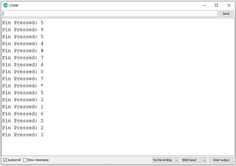
In this program, you can evaluate the performance of this module using the mobile keyboard. By touching each number 0 to 9 and also the # and * symbols, you can see them in the Serial Monitor.
The output is as follows: