MMA7361 Accelerometer Module Features
The MMA7361 is a 3-axis accelerometer with ± 1.5g to ± 6g measuring range. You do not need a library and complex code to use MMA7361 accelerometer. In this module, there is an analog output voltage for each axis acceleration. As a result, you can read and analyze sensor’s outputs using an analog-to-digital converter.
You can download the datasheet of this module here.
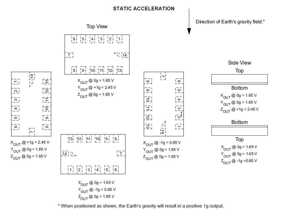
The output voltage for each axis of this module is as follows.
MMA7361 Accelerometer Module Pinout
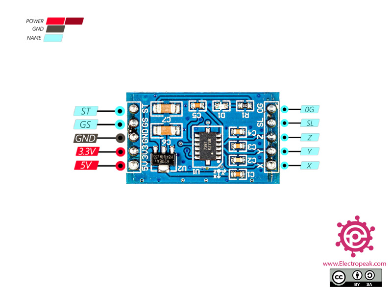
This sensor has 10 pins:
- 5V: Module power supply – 5 V
- 3V3: Module power supply – 3.3V
Note
Use only one of the above two pins as module’s power supply.
- GND: Ground
- GS: Specifies the module working mode. If is “0”, the range is ± 1.5g and if “1”, the range is ±6g.
- ST: To test module automatically
- X: X-axis acceleration output
- Y: Y-axis acceleration output
- Z: Z-axis acceleration output
- SL: Sleep
- 0G: Detects zero acceleration on all axes. This pin is used to detect free fall.
You can see pinout of this module in the image below.
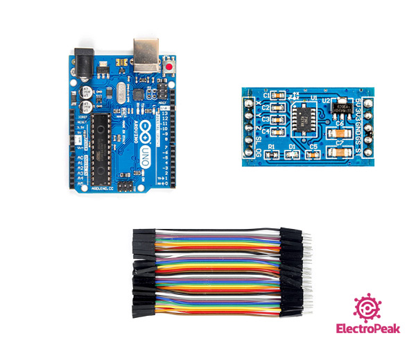
Required Materials
Hardware Components
Software Apps
Interfacing MMA7361 Accelerometer Module with Arduino
Step 1: Circuit
The following circuit shows how you should connect Arduino to MMA7361 module. Connect wires accordingly.
Step 2: Code
Upload the following code to Arduino. This code displays the sensor readings in the serial monitor.
/*
  MMA7361 Accelerometer Sensor
  modified on 21 Sep 2020
  by Mohammad Reza Akbari @ Electropeak
  Home

*/

int x = 0;
int y = 0;
int z = 0;

void setup()
{
  Serial.begin(9600);
}

void loop()
{
  x = analogRead(A0);
  y = analogRead(A1);
  z = analogRead(A2);

  Serial.print("X = ");
  Serial.print(x);
  Serial.print("   X_Voltage = ");
  Serial.println(x*5.0/1024.0);

  Serial.print("Y = ");
  Serial.print(y);
  Serial.print("   Y_Voltage = ");
  Serial.println(float(y)*5.0/1024.0);

  Serial.print("Z = ");
  Serial.print(z);
  Serial.print("   Z_Voltage = ");
  Serial.println(float(z)*5.0/1024.0);

  Serial.println("*******************");

  delay(1000);
}
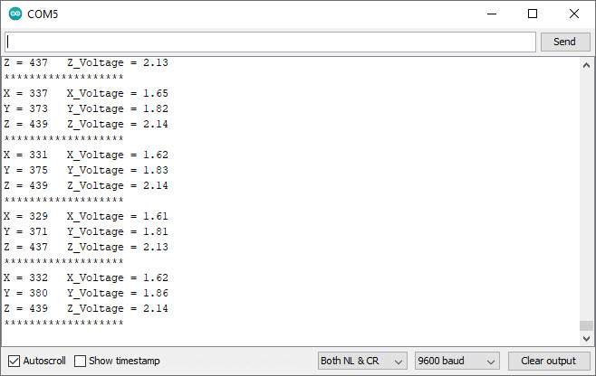
After running the code, you will see the following image in the serial output.
