LM393 Voltage Comparator Module Features
The LM393 amplifier module can be used to compare an input voltage with a predetermined voltage level. The LM393 IC contains 2 op-amps that are completely independent. In LM393 comparator module, only one of the op-amps is used and the other is not connected. The module compares input voltage with the desired voltage level, and produces a digital output. The voltage level can be any value between the module positive and negative supply voltages. This voltage level can be adjusted using the potentiometer on the module.
Note
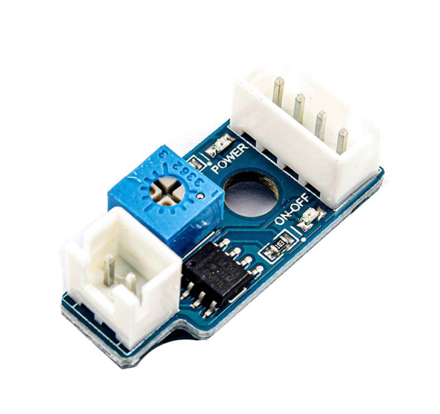
There are two LEDs on the module, one will turn on by module power supply. The other LED is off when the input voltage is lower than the specified voltage level, and turns on when the input voltage is higher.
LM393 Voltage Comparator Module Pinout
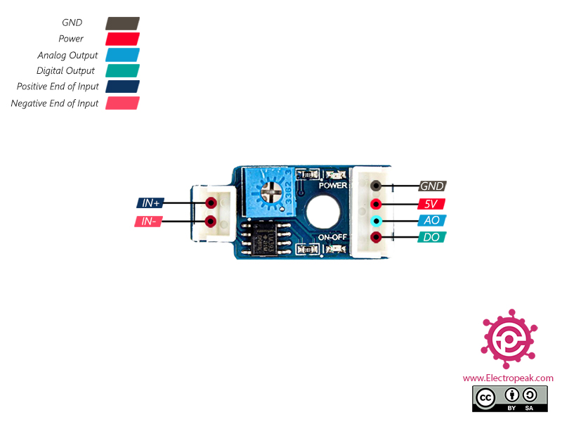
This Module has 6 pins:
4 Pins at the Right Side:
- GND: Ground
- VCC: Module power supply – 5V
- AO: Analog Output
- DO: Digital Output
2 Pins at the Left Side:
- IN+: Input positive side
- IN-: Input negative side
Note
When the input voltage is lower than the specified voltage level, the digital output is LOW and when it is higher, the digital output is HIGH.
The analog output is actually the same as input voltage.
You can see the pinout of this module in the image below.
Required Material
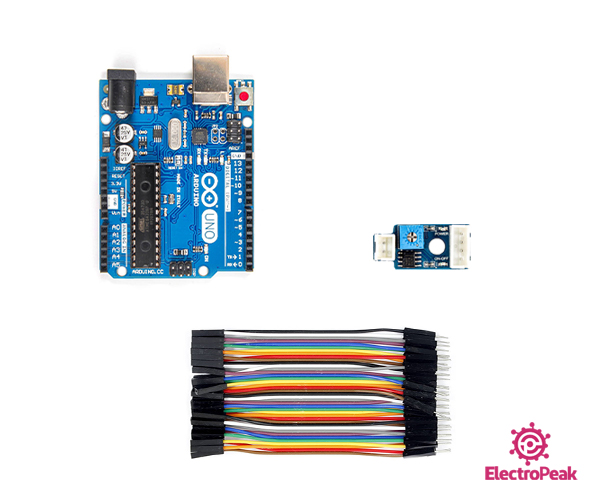
Hardware component
Software Apps
Interfacing LM393 Voltage Comparator Module with Arduino
Step 1: Circuit
The following circuit show how you should connect Arduino to LM393 module. Connect wires accordingly.
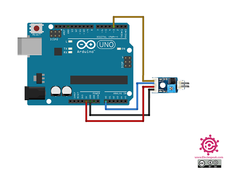
Note
Connect the module to Arduino as said above. The two unconnected pins in the image are actually the input voltage, which can be from any source. In this tutorial in particular, the source is a temperature sensor that has an analog output. To test and observe how the module and code work, the sensor has been alternately put in hot and cold water.
Step 2: Code
Upload the following code to your Arduino. After that open the Serial Plotter.
  /*
  Made on Dec 14, 2020
  By MehranMaleki @ Electropeak
  Home
*/

void setup() {
  Serial.begin(9600);
  pinMode(3, INPUT);
  pinMode(A0, INPUT);
}


void loop() {
  Serial.print(digitalRead(3) * 5); Serial.print("\t");
  Serial.println(analogRead(A0) * 5 / 1024);
  delay(200);
}
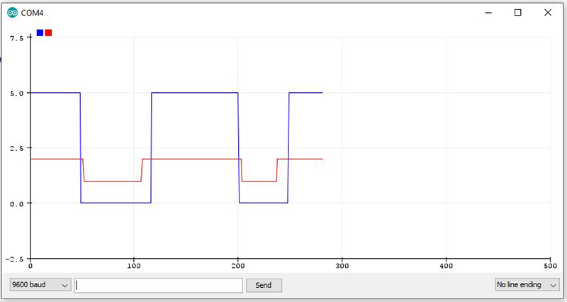
In the above code, the analog and digital outputs are read and shown on Serial Plotter. (The analog output is the the module input, which is actually the output voltage of the temperature sensor.) The voltage level is set around 2.3V.
The output is as follows. The blue graph is the digital output (0V, digital zero and 5V, digital one) and the red graph is the module input voltage. (Which is the analog output voltage of the temperature sensor.)