Interfacing KY-039 Heartbeat Sensor Module with Arduino
Written by
Mehran Maleki
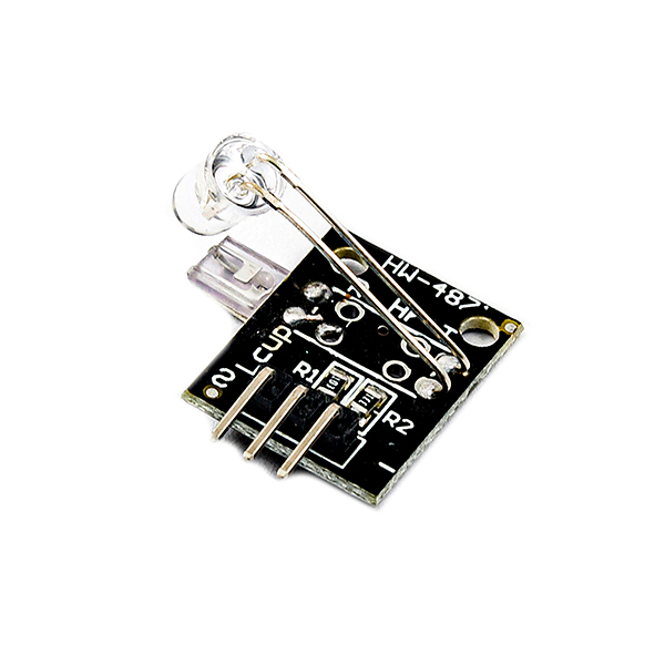
KY-039 Heartbeat Sensor Module Features
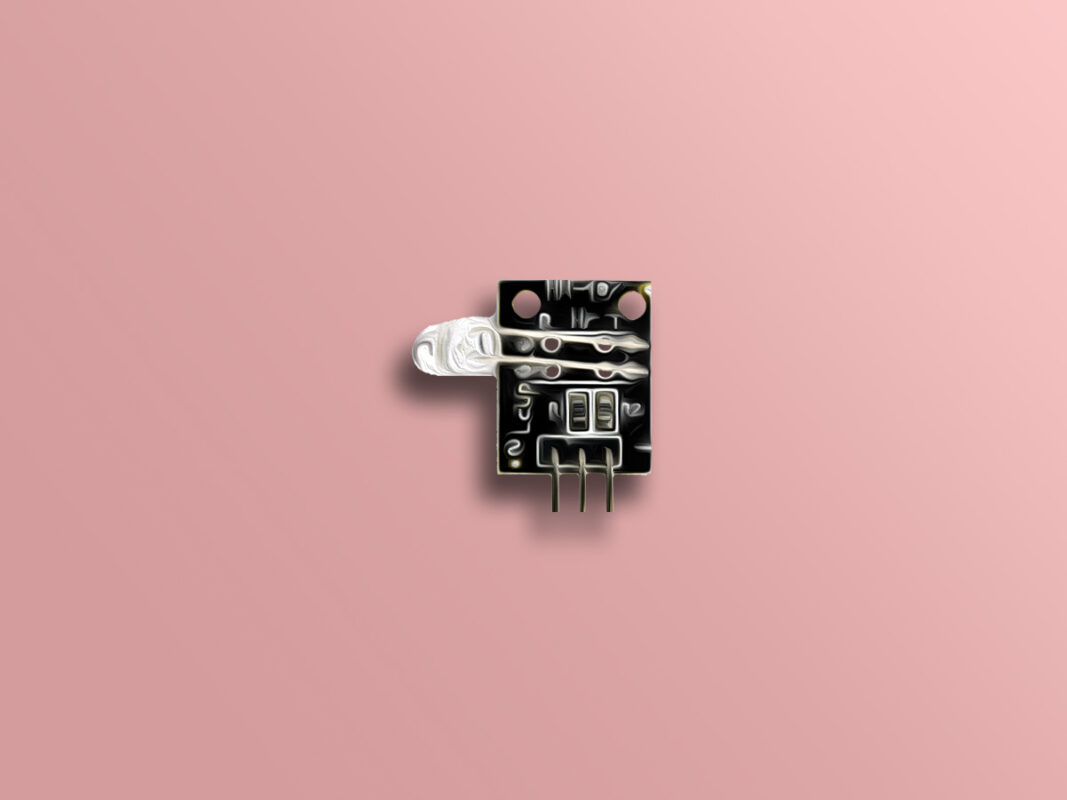
The KY-039 heartbeat sensor module can be used to detect the heartbeat signal using finger. This sensor has an analog output. By placing your finger on the module, you can see the heartbeat signal through the analog output pin.
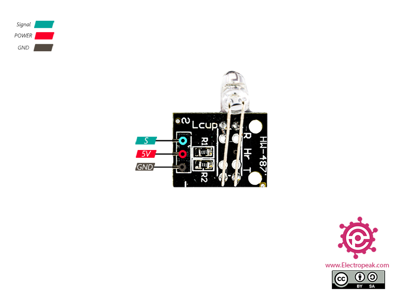
KY-039 Heartbeat Sensor Module Pinout
This module has 3 pins:
S: Analog output signal
VCC: Module power supply – 5V
GND: Ground
You can see the pinout of this module here.
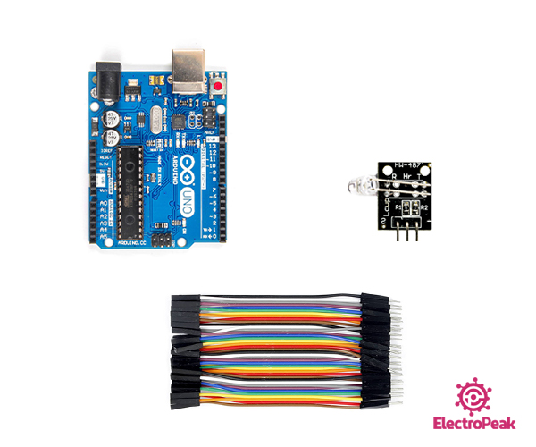
Required Materials
Hardware Components
Arduino UNO R3
×
1
KY-039 Heartbeat Sensor Module
×
1
Male to Female jumper wire
×
1
Software Apps
Arduino IDE
Interfacing KY-039 Heartbeat Sensor Module with Arduino
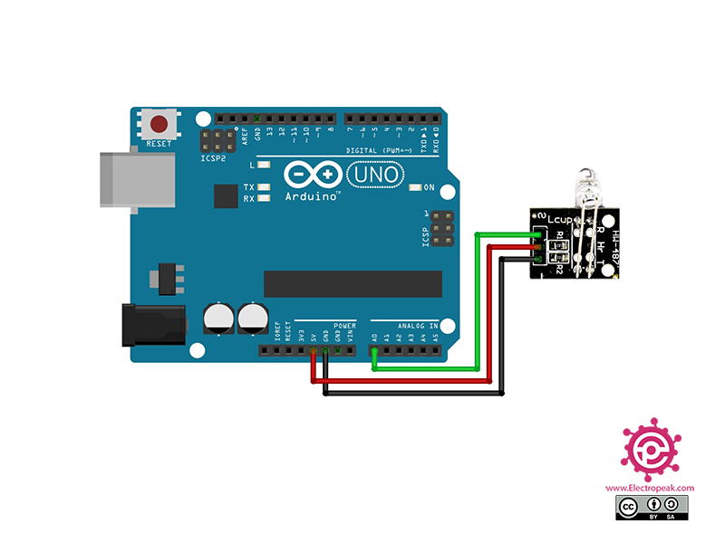
Step 1: Circuit
The following circuit shows how you should connect Arduino to this module. Connect wires accordingly.
Step 2: Code
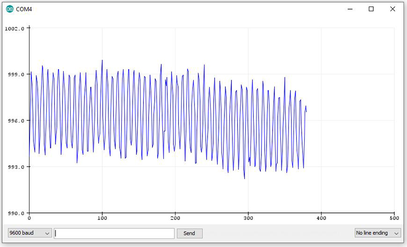
Upload the following code to Arduino. After that open the Serial Plotter.
/*
Made on Jan 16, 2021
By MehranMaleki @ Electropeak
*/
void setup() {
pinMode(A0, INPUT);
Serial.begin(9600);
}
void loop() {
float pulse;
int sum = 0;
for (int i = 0; i < 20; i++)
sum += analogRead(A0);
pulse = sum / 20.00;
Serial.println(pulse);
delay(100);
}
In this code,pin A0 of Arduino is used to receive the analog output data. In order to reduce the effect of noise on output, the average of last 20 output data is used. By placing your finger on the module, you can see how it works.
I’m a student in digital health, and I need your urgent help with my project.I am wondering how I can contact you for more explanation, please.I really appreciate your help in advance.
Hi,
Unfortunately, you cannot use this exact code to calculate the BMP value and you need to add a few lines of codes to it. First, you should define a threshold, say around 996. Then, you should use the “millis” function or a timer to calculate a certain amount of time like 100 mS or 1S. Then, you declare in integer named “counter”. Finally, you can compare the output voltage of the sensor with the defined threshold and increment the “counter” variable whenever the output voltage of the sensor is greater than the threshold. You should then use the “counter” calculated in the certain amount of time measured by the “millis” function of the timer to calculate the BPM value. The following article might help you too. https://electropeak.com/learn/interfacing-heart-rate-sensor-module-with-arduino/


Comments (4)
Hi Mehran,
I’m a student in digital health, and I need your urgent help with my project.I am wondering how I can contact you for more explanation, please.I really appreciate your help in advance.
Hi.
You can briefly ask your question here. I’d be glad to help.
Hello Mehran,
how can I calculate from your code the bpm-value? Can you help us in this topic?
Thank you very much for posting your code and taking the time to help us
Thank you very much in advance
Best regards
Kosta
Hi,
Unfortunately, you cannot use this exact code to calculate the BMP value and you need to add a few lines of codes to it. First, you should define a threshold, say around 996. Then, you should use the “millis” function or a timer to calculate a certain amount of time like 100 mS or 1S. Then, you declare in integer named “counter”. Finally, you can compare the output voltage of the sensor with the defined threshold and increment the “counter” variable whenever the output voltage of the sensor is greater than the threshold. You should then use the “counter” calculated in the certain amount of time measured by the “millis” function of the timer to calculate the BPM value. The following article might help you too.
https://electropeak.com/learn/interfacing-heart-rate-sensor-module-with-arduino/