
Introduction
Are you looking to enhance your smart and security systems? Want to create projects that detect motion and automate your home? Look no further! Introducing the HW-MS03 motion detection module, a powerful radar sensor that can revolutionize your projects. Whether you want to secure your premises, automate lighting systems, or develop cutting-edge applications, this module is your key to unlocking endless possibilities.
The basic task of these sensors, as you can guess by their name, is to detect moving objects (or living creatures). For this, various sensors and modules with a wide variety of measurement accuracies and ranges have been designed and produced. In fact, radar systems—which are frequently used in shipping, air transport, and military sectors—are thought to belong to this family of sensors.
In this comprehensive guide, we will walk you through the process of interfacing the HW-MS03 module with Arduino. You will learn the ins and outs of this microwave-based motion detection technology, its specifications, and step-by-step instructions to set it up effectively. Get ready to embark on an exciting journey of creativity and innovation.
Get ready to take control of your projects and explore the fascinating world of motion detection with the HW-MS03 module and Arduino.
HW-MS03 Radar Module: An Introduction
Microwaves and Their Applications
Microwaves are a type of electromagnetic radiation with a wavelength between one meter and one millimeter and a frequency between 300 MHz and 300 GHz is referred to as a microwave.
The full spectrum of electromagnetic waves, of which microwaves are one kind, is shown below. Microwaves have lower energy and frequency compared to visible light because their wavelengths are longer.
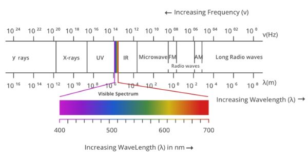
Moreover, these electromagnetic waves are used in radar, remote sensors, communications, space science, and, of course, cooking devices.
This article focuses on the use of microwaves in radars, which is employed in HW-MS03 modules.
Understanding Radar
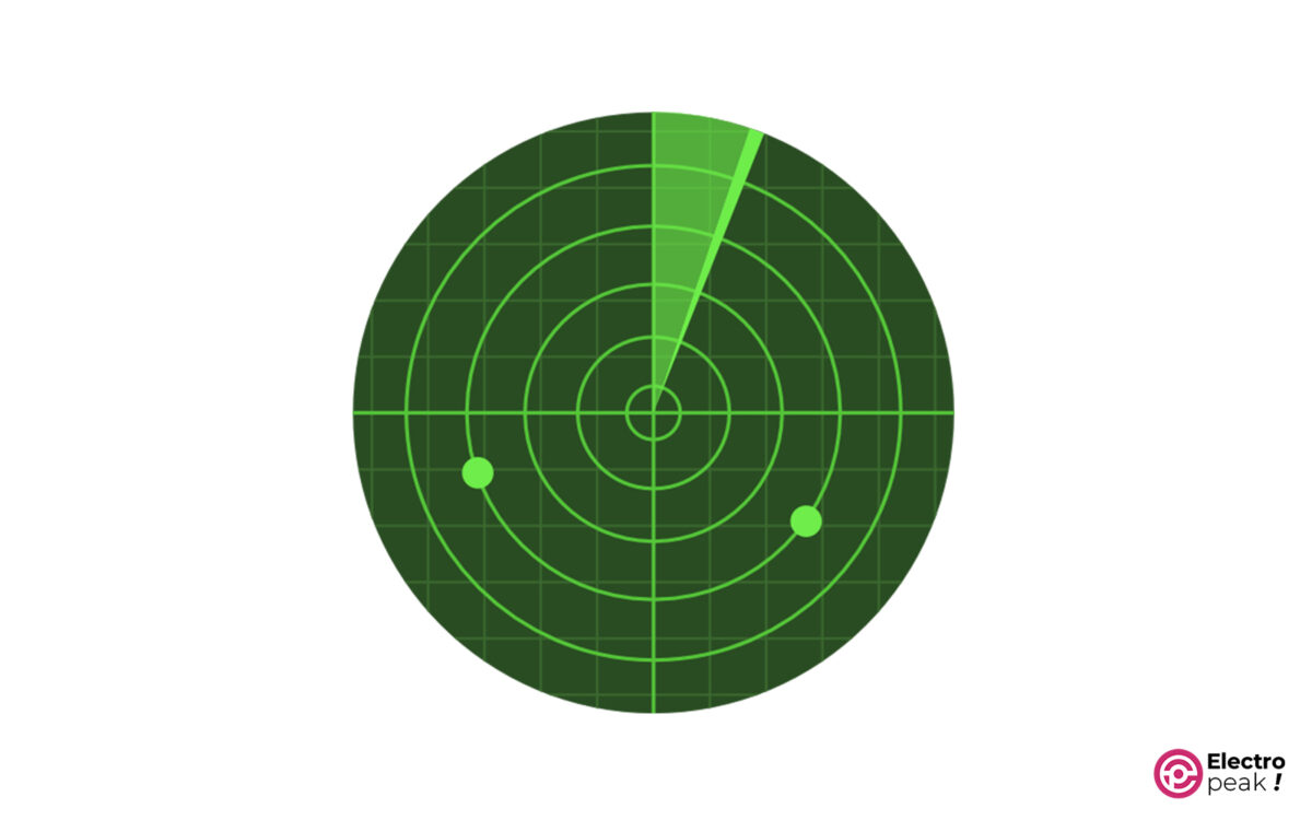
Radar, short for Radio Detection and Ranging, is a technique that determines data such as an object’s distance and speed by transmitting an electromagnetic wave and receiving its reflection from a reflective source.
This technology is widely used in the military, defense, shipping, air transport, oil, and gas industries, to name a few. You might find it interesting to know that radars are also used by speed cameras.
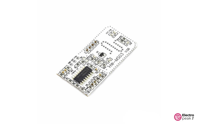
HW-MS03 Radar Module
HW-MS03 module, as the name implies, is a radar sensor that can detect moving objects.
It works by activating its output pin whenever a moving object is detected within the sensor’s range and deactivating it after a certain amount of time if no moving objects are detected. You can use them in household items, security systems, lighting systems, etc., by connecting the sensor output to a microcontroller or directly to control circuits such as relays.
The power supply voltage of this module ranges from 3.7 to 24 volts and its output pin voltage is 3.3 volts (when active).
This module generates waves with frequencies between 2.5 and 5.8 GHz, and its detecting area is a sphere with a 10-meter radius.
Specifications of HW-MS03 Module
Here are the specifications of the HW-MS03 module:
- Input voltage: 3.7 to 24 volts
- Input current: less than or equal to 6 mA
- Output voltage: 3.3 volts (when active)
- Measuring range: 10 meters (tested in a closed space)
- Output delay: normally 2 seconds
- Working frequency: 2.5 to 5.8 GHz
- Dimension: 20 x 40 mm
HW-MS03 Module Pinout
The HW-MS03 module has only 3 pins:
- VCC: module power supply (3.7 to 24 volts)
- GND: Ground
- OUT: output pin (3.3V Active High)

Required Materials
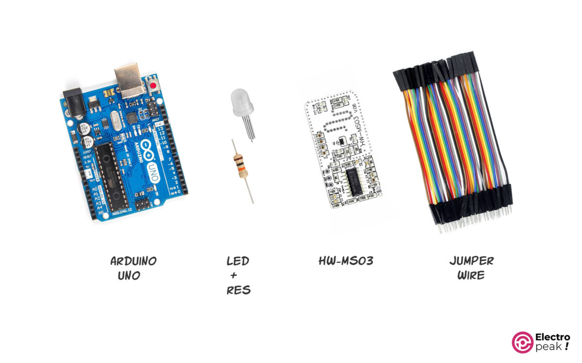
Hardware Components
Software
Interfacing HW-MS03 Motion Detection Module with Arduino
Step 1: Wiring
Connect the HW-MS03 module to the Arduino board as shown below.

Step 2: Code
Copy and run the following code in Arduino. This code turns on an LED when the module’s radar detects movement and turns it off when there is no motion.
#define Radar_pin 2

#define LED_pin 4

volatile byte state = LOW;   // variable to define the state of Radar_pin

void setup() {

    Serial.begin(9600);

    pinMode(Radar_pin,INPUT_PULLUP);

    pinMode(LED_pin, OUTPUT);

    attachInterrupt(digitalPinToInterrupt(Radar_pin), radar_change, CHANGE);

    //due to any change on Radar_pin, radar_change Function will be called

}

void loop() {

    digitalWrite(LED_pin, state);

    /*

    YOUR OTHER CODE

    */

}


void radar_change(){     // Interrupt ISR

  state= digitalRead(Radar_pin);

  if (state==1) Serial.println("Motion Detected");

  else Serial.println("There is No Motion");
}
With the help of the above code, the LED will be turned on if the module’s radar detects movement and off if there is no motion.
A brief explanation of the above code:
At first, Pins 2 and 4 are defined as digital input and output, respectively. The output of the radar sensor is connected to Arduino’s pin 2 and the anode pin of the LED is connected to Arduino’s pin 4.
By configuring an interrupt routine to pin 2 in the following line, the “radar change()” function will be called whenever the pin state changes.
attachInterrupt(digitalPinToInterrupt(Radar_pin), radar_change, CHANGE);
By calling the “radar_change()” function, the state of pin 2 is read as output and stored in the state variable (zero or one). Also, a message is displayed on the serial port, indicating whether or not the motion is detected by examining the input state.
Then, in the main loop, with the command digitalWrite(LED pin, state);, pin 4, which was previously defined as the output for the LED pin, is set to High or Low based on the state variable.
Keep in mind that on Arduino UNO, we can only enable interrupt routines for pins 2 and 4.
What’s Next?
At first, Pins 2 and 4 are defined as digital input and output, respectively. The output of the radar sensor is connected to Arduino’s pin 2 and the anode pin of the LED is connected to Arduino’s pin 4.
By configuring an interrupt routine to pin 2 in the following line, the “radar change()” function will be called whenever the pin state changes.
