L9110 Dual Channel Driver Module Features
Motor driver modules are very common nowadays and widely used to control the speed and direction of motors. The L9110S dual channel module is one of them. This module can control two DC motors and one stepper motor. It is based on L9110 IC. The key features are:
- The allowable continuous current for each channel: 800mA.
- The operating voltage: 2.5 – 12V.
- Two control pins for each DC motor.
- Suitable for toy cars motors.
- Can control one stepper motor.
Note
This module can only be used to control the direction of motors rotation.
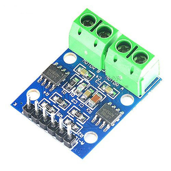
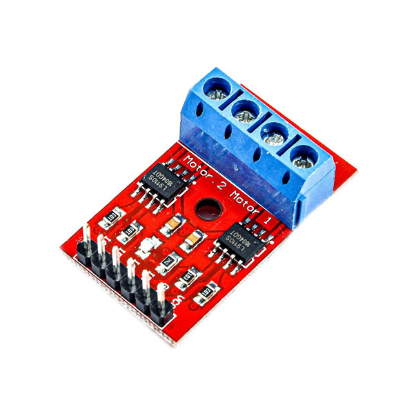
You can see two similar modules based on L9110 IC in the pictures below.
You can download the datasheet of L9110 IC here.
HG7811/L9110 Motor Drive Module Pinout
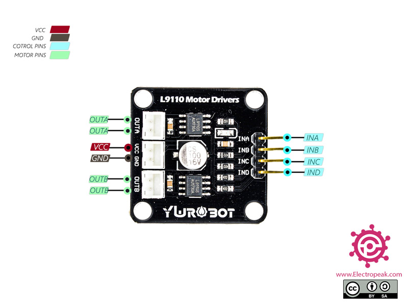
This module has 8 pins:
- VCC: Module power supply
- GND: Ground
- OUTB: Motor B
- OUTA: Motor A
- INA: First pin to control motor A
- INB: Second pin to control motor A
- INC: First pin to control motor B
- IND: Second pin to control motor B
You can see the pinout of this module in the image below.
Note that with different operating modes, the performance will change. This table shows different modes.

Required Materials
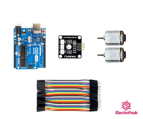
Hardware Components
Software Apps
Interfacing HG7811/L9110 Motor Drive Module with Arduino
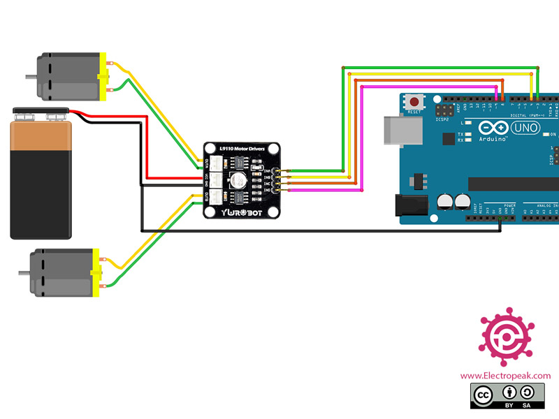
Step 1: Circuit
Note
Warning
Be careful not to use more than 6V power supply, because these motors are 6V DC motors.
Step 2: Code
Upload the following code to your Arduino.
   /*
  YwRobot-L9110-Dual-Motor-Drive
  made on 24 Nov 2020
  by Amir Mohammad Shojaee @ Electropeak
  Home

*/
#define AIN1 3
#define AIN2 4
#define BIN1 8
#define BIN2 9

void setup() {
  Serial.begin(9600);

  pinMode(AIN1,OUTPUT);
  pinMode(AIN2,OUTPUT);
  pinMode(BIN1,OUTPUT);
  pinMode(BIN2,OUTPUT);
}

void loop() {
  digitalWrite(AIN1,HIGH);
  digitalWrite(AIN2,LOW);
  digitalWrite(BIN1,HIGH);
  digitalWrite(BIN2,LOW);

  delay(2000);

  digitalWrite(AIN1,LOW);
  digitalWrite(AIN2,HIGH);
  digitalWrite(BIN1,LOW);
  digitalWrite(BIN2,HIGH);

  delay(2000);

}
By uploading this code, the motor first starts rotating clockwise for 2 seconds, then rotates in the opposite direction for 2 seconds.
