
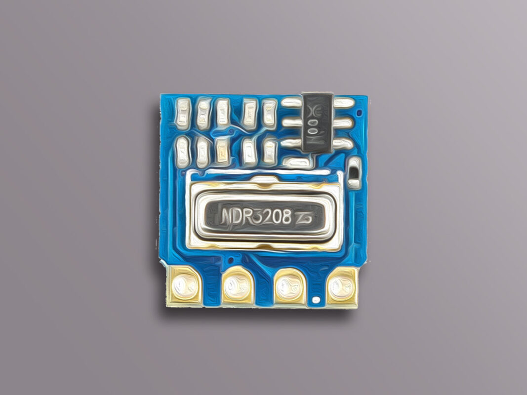
H34A Wireless Transmitter Module Features
Electronic devices need to be connected wirelessly in so many cases. In such cases, Radio Frequency or RF equipments are used. RF modules include all radio waves that can travel different distances and reach the receiver according to their frequency and amplitude.
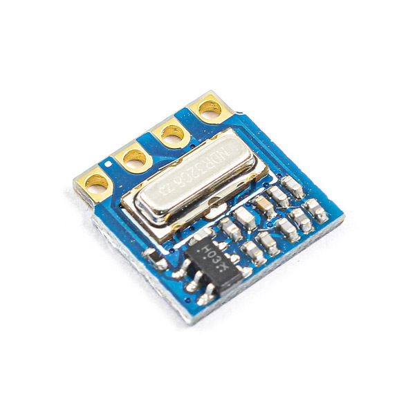
The H34A module is produced in two different types: 315MHz and 433MHz.
Note
All modules that use the 315/433MHz frequency band can communicate with each other and there is no information security in this type of communication. If you need security, you must use encryption (locking) on the receiver and transmitter.
Note
This module is only a transmitter and cannot receive data. So, on the receiver side, we use one type of radio receiver according to the transmitter frequency.
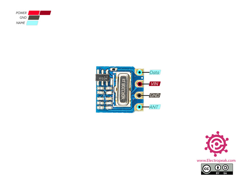
H34A Wireless Transmitter Module Pinout
This module has 4 pins:
- VIN: Module power supply
- GND: Ground
- Data: Data line for sending or transmitting
- ANT: Antenna (connection is optional)
Required Materials
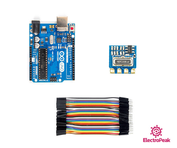
Hardware Components
Software Apps
Interfacing H34A Wireless Transmitter Module with Arduino
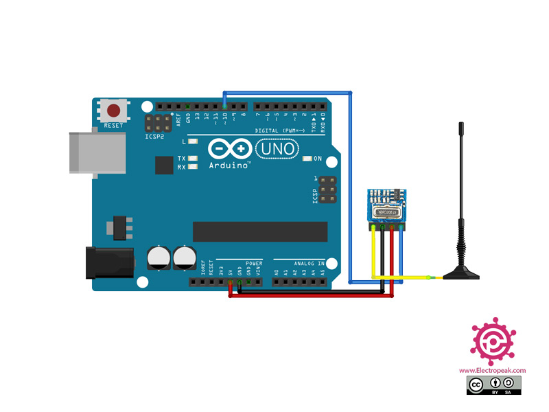
Step 1: Circuit
The following circuit shows how you should connect the Arduino Board to the H34A module. Connect wires accordingly.
Step 2: Library
Install the following library on your Arduino IDE.
Tip
If you need more help with installing a library on Arduino, read this tutorial: How to Install an Arduino Library
Step 3: Code
Upload the following code to your Arduino.
/*
  Example for different sending methods

  https://github.com/sui77/rc-switch/

*/

#include <RCSwitch.h>

RCSwitch mySwitch = RCSwitch();

void setup() {

  Serial.begin(9600);

  // Transmitter is connected to Arduino Pin #10
  mySwitch.enableTransmit(10);

  // Optional set protocol (default is 1, will work for most outlets)
  // mySwitch.setProtocol(2);

  // Optional set pulse length.
  // mySwitch.setPulseLength(320);

  // Optional set number of transmission repetitions.
  // mySwitch.setRepeatTransmit(15);

}

void loop() {

  /* See Example: TypeA_WithDIPSwitches */
  mySwitch.switchOn("11111", "00010");
  delay(1000);
  mySwitch.switchOff("11111", "00010");
  delay(1000);

  /* Same switch as above, but using decimal code */
  mySwitch.send(5393, 24);
  delay(1000);
  mySwitch.send(5396, 24);
  delay(1000);

  /* Same switch as above, but using binary code */
  mySwitch.send("000000000001010100010001");
  delay(1000);
  mySwitch.send("000000000001010100010100");
  delay(1000);

  /* Same switch as above, but tri-state code */
  mySwitch.sendTriState("00000FFF0F0F");
  delay(1000);
  mySwitch.sendTriState("00000FFF0FF0");
  delay(1000);

  delay(20000);
}
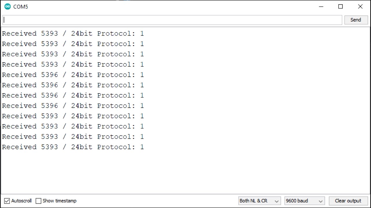
This code is to test the connection between the transmitter and receiver.
The receiver can see the sent data in the Serial monitor.

Comments (2)
I am introducing in the knowledge of Arduino and its applications.
That’s great to hear! Good luck.