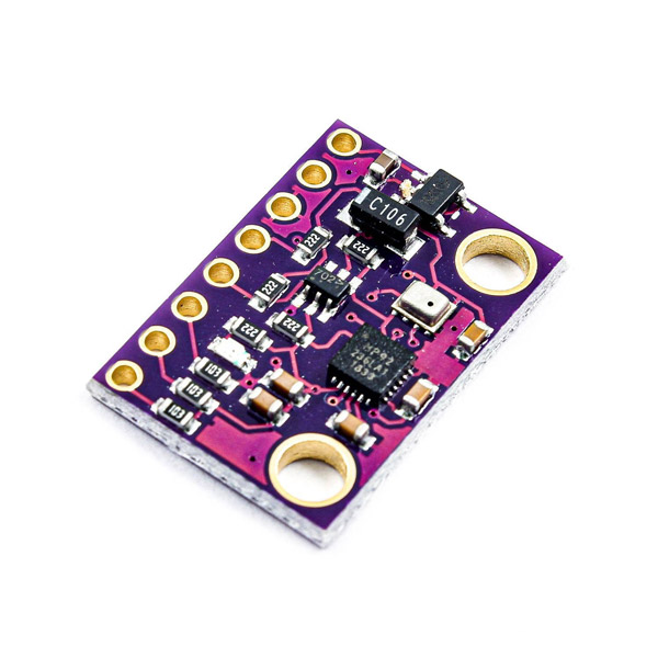
You can download the datasheet of this module here.

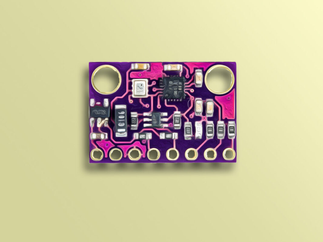
You can download the datasheet of this module here.

Comments (26)
acelerometro:17:14: error: ‘SDA_PIN’ was not declared in this scope
acelerometro:17:23: error: ‘SCL_PIN’ was not declared in this scope
Just to improve your tutorial. Thank you for the post!
Hello.
The code was originally written for an Arduino Board. If you’re planning to use it for an ESP32 Board, then you need to define SDA and SCL pins on your own.
Hallo, thanks for your code.
I use mCore (ATmega328) with GY-91 wired to pin SDA and SCL of port 3.
So I can read MPU9250 data but anything about BMP280.
May be I have to wire it to another PINs (I tried with 11,12,A0,A1) but I don’t know which ones.
Can you help me, please?
Thank you!
Hi
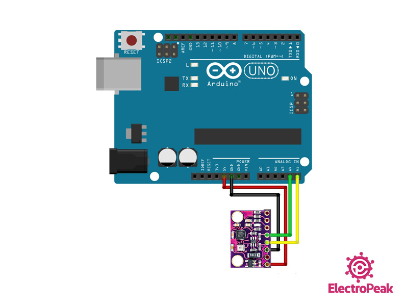
BMP280 and MPU9250 both use I2C communication protocols, but they have different I2C addresses and can use the same I2C bus for communication. So now that you have connected the GY-91 module to the I2C pins of your microcontroller, no more wiring is needed. You can access both BMP280 and MPU9250 through those pins. You just need to use the appropriate libraries for that.
Hello, great code, thank you for it.
I am using arduino Mega and GY91 bought on aliexpress.
However, only gyro’s data is changing on serial display. Do I have to modify something in libraries (adresses maybe ?) in order to access the full data ?
Thank you
Hi. The tutorial here is based on Arduino Uno, but there shouldn’t be any difference in the code when using your module with Arduino Mega. Just keep in mind that the Arduino Mega I2C pin are A20 and A21. (SDA and SCL respectively) So that’s the only difference you should pay attention to when interfacing the module with Arduino Mega, and you should get the same results as here. If you don’t, there can be something wrong with the GY-91 module. To check the functionality of the sensor, you can use i2c_scanner code provided in Arduino IDE examples → Wire → i2c_scanner and see the i2c addresses it returns.
Hello, great code,
I am using Arduino/Teensy and this module GY-91
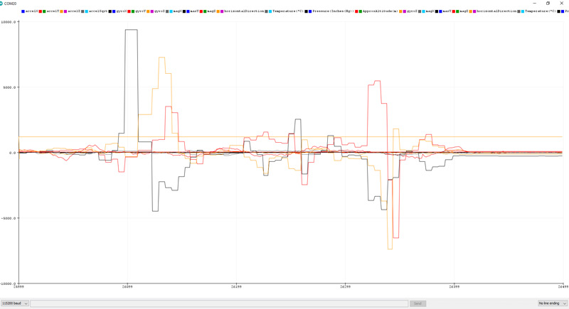
i am getting this values for AccelX and AccelY. Here is link: https://www.hizliresim.com/rn7afp9
Can you help me?
Thanks .
Hello my friend,
When the values of some particular parameters don’t change, it usually means that there is something wrong with the module. Try to find some other library and code and compare the results. If nothing changed and the problem still persisted, you’ll probably need to get a new module.
Good luck.
Hello. Really nice tutorial and code.
However, I am running into one problem.
The mpu9250 is giving me good values for accel, gyro, and mag, but the bmp280 is giving me nothing. Temp reads 0.00, pressure reads 0.00 which causes the alt to read 44330.00. I have tried three different gy-91s and all three gave me the same result.
I thought at first it might be the library, so I tried a different library but received the same result. Because a library change didn’t do anything and the wiring is obviously correct since the mpu9250 works, that leaves me to conclude that the problem is in the gy-91 itself. However, I could understand one of them being defective, but all three?!
I am hoping I just missed something somewhere rather than buying 3 defective gy-91s.
Thank you for your time.
Hello. Thanks for your exhaustive explanation of your problem! According to what you have already done, there is little I can add to that. There is just one other thing you haven’t check. Use the “i2c_scanner” code to check what addresses it returns. To find this code, open the Arduino IDE. You can see the code in “File → Examples → Wire → i2c_scanner”. Using this code, you can find out what I2C devices are connected to your Arduino Board. The I2C address of the BMP280 sensor is 0x76 of 0x77. If the i2c_scanner doesn’t return an address like that, then the modules might be defective. Hope that helps! Good luck.
Joshua, your problem is possibly that you need to set the address of the BMP 280 on line 21. Change line 21 in the code above from:
bme.begin();
to:
bme.begin(0x76); // Assumes GY-91’s BMP 280 is at default address
This worked for me with a GY-91 attached to a TeensyDuino 3.2 after reading https://github.com/adafruit/Adafruit_BME280_Library/issues/15 and running Wire -> Scanner with Scanner set up for a Teensy’s I2C pins.
My mag reading is stuck at zero but that is a separate problem.
J
thanks, now it is working
Hello, I want to know how to get accel, gyro, and mag. The three infos are all 0 in my computer. After seeing Mr. Maleki’s method, I key in 0x76 and get correct infos of temperature, pressure and altitude. But there’s still a problem to accel, gyro, and mag. Thank you.
In file included from accel_WR.ino:4:0:
C:\Users\Maheek Fatima\Documents\Arduino\libraries\Adafruit_BMP280_Library/Adafruit_BMP280.h:24:29: fatal error: Adafruit_Sensor.h: No such file or directory
#include “Adafruit_Sensor.h”
^
compilation terminated.
Error compiling.
if anyone can help!
Hi,
I just compiled the code to make sure there is no error, and there was none. Make sure you have installed the 2 libraries discussed in the tutorial. Also, make sure you have the “Adafruit Unified Sensor” library installed on your Arduino IDE. It’s a library that a lot of other libraries such as the 2 libraries in this article use. To install it, open your Arduino IDE. Go to “Tools → Manage Libraries”. Type “Adafruit Unified Sensor” in the search box, scroll down to find the “Adafruit Unified Sensor” library and install it. That must solve your problem.
Excelent..Excelent..Excelent..!!!!!
Thank you for your generous comment! You’re most welcome.
I just have included this code to my arduino IDE, did 100% the same things as the post said, and I’m having trouble showing the result on the serial monitor, it keeps showing me random letters. Can u pls help me? just don’t know what I did wrong.
Hi,
This often happens when the baudrate of the Serial Monitor is not set to the right value. Make sure the baudrate is set to 115200.
Hello, thank you for the response, I changed the baudrate to 115200 and this especific problem was solved. But another one came up, the serial print of the accelerometer, gyroscope and magnetometer are not appearing on the serial monitor, only the pressure, temperature and alttitude are appearing, but with “nan” as a result, just like this print shows you: https://imgur.com/kyhAivA. I’m sorry for bothering again but I hope you can help me.
Thanks again.
You’re welcome! And about your new problem, you have either not connected the sensor to the Arduino properly, or there is something wrong with the sensor itselt. So, first, double check the wiring.
Hello,
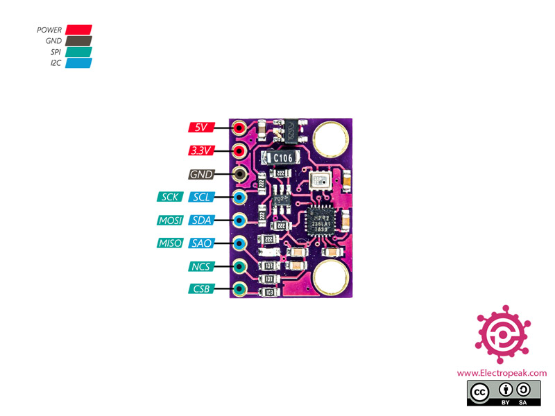
I have a question about the GY-91 board. How are the CSB and NCS pins connected?
Gyro delivers good results, the BME280 cannot be initialized.
thanks
Hi. Thank you for the tutorial you sent. I also had this issue where my sensor would print “NaN”. As you said to the other guy, I checked my wiring, and it looks fine, but it still prints “NaN’. Do you mind solving this issue? I am using an Arduino GIGA R1 and my SDA is connected to its SDA1 pin and SCL to SCL1 pin. Then I connected to 5V and GND pins. I even tried connecting the SDA and SCL to A4 and A5, but it still printed “NaN”. Do you mind helping me.
Hi Shivan,
Start by utilizing the I2C Scanner available under “File → Examples → Wire → i2c_scanner” to verify the wiring.
For the Arduino GIGA R1, note that it features 3 I2C ports, with the default pins being 20 (SDA) and 21 (SCL). To initialize I2C1, use Wire1.begin(), and for I2C2, utilize Wire2.begin().
Once you receive the ID from the sensor, ensure to cross-check it in the code.
i tried your code but i have problem:
(58501) i2c.master: I2C transaction unexpected nack detected
E (58502) i2c.master: s_i2c_synchronous_transaction(924): I2C transaction failed
E (58509) i2c.master: i2c_master_multi_buffer_transmit(1186): I2C transaction failed
Temperature(*C): nan Pressure(Inches(Hg)): nan ApproxAltitude(m): nan
accelX: 0.18 accelY: 0.01 accelZ: 1.07 accelSqrt: 1.09 gyroX: -6.90 gyroY: 1.95 gyroZ: 7.63E (58539) i2c.master: I2C hardware NACK detected
E (58539) i2c.mas
Hello Maulana,
please make sure all wires are connected correctly. You can also use an I2C scanner to check if the device is properly detected and the wiring is correct.