GY-31 TCS3200 Color Sensor Features
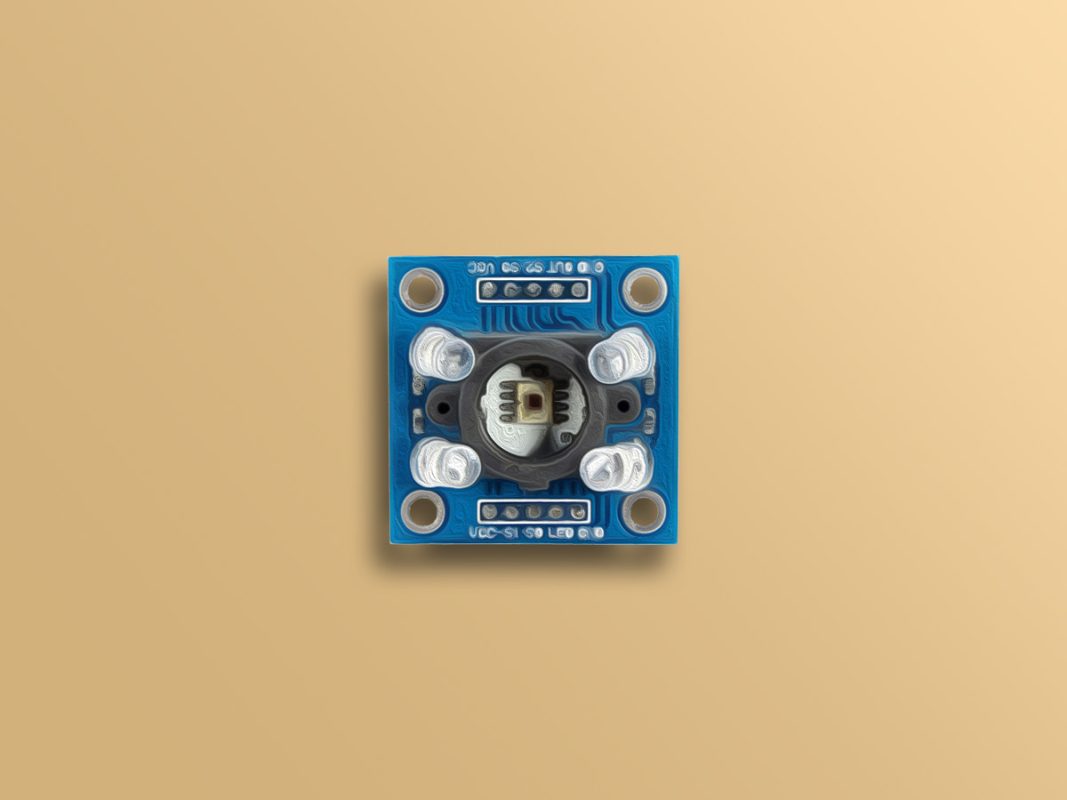
The TCS3200 color sensor uses 64 photodiodes to detect color. The output of this sensor is a square wave. Color intensity is obtained directly from the frequency of the square wave. These 64 photodiodes consist of 16 diodes with red filter, 16 diodes with green filter, 16 diodes with blue filter and 16 transparent photodiodes without filter. All 16 diodes of each type are connected in parallel. To detect any color, the photodiodes corresponding to that color are activated.
You can download the datasheet of this module here.
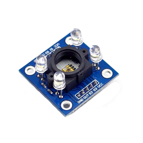
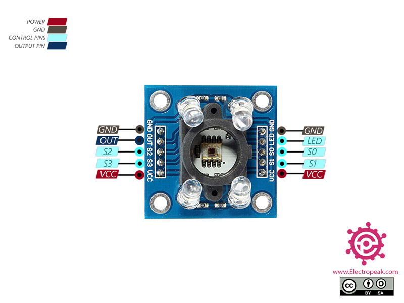
GY-31 TCS3200 Color Sensor Pinout
This Module has the following pins:
- VCC: Module power supply – 2.7V to 5.5V
- GND: Ground
- OUT: Output signal
Control pins:
- S0: Output Frequency Scaling Selection Input
- S1: Output Frequency Scaling Selection Input
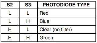
- S2: Photodiode Type Selection Input
- S3: Photodiode Type Selection Input
- LED: LED control
Note
Pins S2 and S3 are used to select one of the 4 photodiode types. Take a look at the table below.
Note
Pins S0 and S1 are used for scaling the output frequency. Take a look at the table below.
You can see the pinout of this module in the image below.
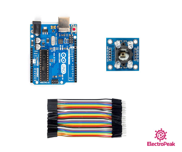
Required Material
Hardware component
SoftwarenApps
Interfacing GY-31 TCS3200 Color Sensor with Arduino
Step 1: Circuit
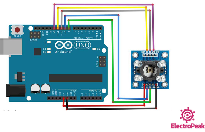
The following circuit show how you should connect Arduino to TCS3200 sensor. Connect wires accordingly.
Step 2: Code
Upload the following code to your Arduino.
    /*
  GY-31-TCS3200-Color-Recognition-Sensor-Module
  Modified on 29 Dec 2020
  by Amir Mohammad Shojaee @ Electropeak
  Home

  based on create.arduino.cc Example
*/

#define s0 8
#define s1 9
#define s2 10
#define s3 11
#define out 12

int data=0;

void setup()
{
   pinMode(s0,OUTPUT);
   pinMode(s1,OUTPUT);
   pinMode(s2,OUTPUT);
   pinMode(s3,OUTPUT);
   pinMode(out,INPUT);

   Serial.begin(9600);

   digitalWrite(s0,HIGH); //Putting S0/S1 on HIGH/HIGH levels means the output frequency scalling is at 100% (recommended)
   digitalWrite(s1,HIGH);

}

void loop()                  //Every 0.2s we select a photodiodes set and read its data
{

   digitalWrite(s2,LOW);        //S2/S3 levels define which set of photodiodes we are using LOW/LOW is for RED LOW/HIGH is for Blue and HIGH/HIGH is for green
   digitalWrite(s3,LOW);
   Serial.print("Red value= ");
   data=pulseIn(out,LOW);  //here we wait until "out" go LOW, we start measuring the duration      and stops when "out" is HIGH again
   Serial.print(map(data,60,15,0,100));
   Serial.print("\t");
   delay(20);

   digitalWrite(s2,LOW);
   digitalWrite(s3,HIGH);
   Serial.print("Blue value= ");
   data=pulseIn(out,LOW);  //here we wait until "out" go LOW, we start measuring the duration and stops when "out" is HIGH again
   Serial.print(map(data,80,11,0,100));
   Serial.print("\t");
   delay(20);

   digitalWrite(s2,HIGH);
   digitalWrite(s3,HIGH);
   Serial.print("Green value= ");
   data=pulseIn(out,LOW);  //here we wait until "out" go LOW, we start measuring the duration and stops when "out" is HIGH again
   Serial.print(map(data,80,20,0,100));
   Serial.print("\t");
   delay(20);

   Serial.println();

   delay(200);
}
First, we declare four outputs for the 4 control pins of the sensor and then one input for the sensor output pin. Next, we determine the output frequency scaling using pins S0 and S1. Then we select color using pins S2 and S3. Next, with the pulseIn command, we get the intensity of three colors: red, blue and green, and display them on the Serial Monitor.
Note
We can calibrate the sensor output pulse using the map command and make the color intensity range from 0 and 100.
To do this, we must first place sensor in a completely stable position and then open the Serial Monitor and place the red, green and blue papers in front of the sensor, respectively. We write the range of each color and convert this range to values from 0 to 100 using map command.
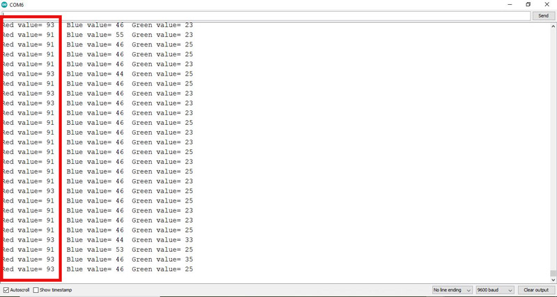
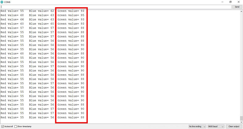
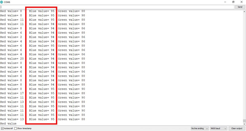
You can see the output of Serial Monitor when we place the three colors red, green and blue papers in front of the sensor, respectively.
Output of Red color:
Output of Green color:
Output of Blue color:
