Contents

Interfacing GY-25 3-Axis Accelerometer & Gyroscope Module with Arduino

GY-25 Module Features

The GY-25 sensor module is a high-resolution 3-axis sensor based on the MPU6050 sensor. It includes a 3-axis gyroscope and a 3-axis accelerometer, all in the MPU6050 sensor chip.
The GY-25 module also has a microcontroller called the 32F030F4P6. Its role is to process and convert data from the MPU6050 sensor to obtain the angle value.
The microcontroller and Arduino board communicate with the GY-25 module through the UART interface. In addition, the GY-25 module has an I2C interface for reading raw data from the MPU6050 sensor. You can choose the type of communication by the two jumper pads on the board and short-circuiting them will activate the I2C interface. Two other jumper pads allow you to set the baud rate between 9600 and 115200.
The GY-25 module operates at a voltage range of 3-5V, suitable for both 3.3V and 5V modes.

GY-25 Module

GY-25 3-Axis Accelerometer & Gyroscope Module Specifications

• Measuring range of axes: -180 to +180 degrees
• Resolution: 0.01 degrees
• Frequency Response: 100HZ (115200bps)
• Operating Current: 15 mA
• Operating Temperature: -20 to 85 °C
• Dimensions: 15.5mm*15.5mm

MPU6050 Datasheet

32F030F4P6 Microcontroller Datasheet

GY-25 Pinout

The GY-25 module has eight pins:
• VCC: power (3-5v)
• RX: receive serial data 
• TX: transmit serial data 
• GND: Ground
• RST: Reset (Internal use)
• B0: Internal use
• SCL: I2C clock
• SDA: I2C data line

GY-25 Pinout

Required Materials

Required Materials

Hardware Components

Arduino UNO R3 × 1
GY-25 3-Axis Accelerometer and Gyroscope Module × 2
Jumper Wire × 3

Software

Arduino IDE

Interfacing GY-25 Gyroscope & Accelerometer Module with Arduino

Virtual UART Definition in Arduino

When hardware UART is not available or more interfaces are required, we must use the software UART.
Here are the steps you should follow:
SoftwareSerial library installation: Click here to download the library zip file.
If you need more help with installing the library, click on this link.
Configuration of Virtual UART Pins:

static const int RXPin = 8, TXPin = 7; // announce your Rx and Tx pins
SoftwareSerial newserial(RXPin, TXPin); // "newserial" is our software serial port

The code above creates a new serial communication port, configuring pin 8 as TX and pin 7 as RX.
Configuring the new baud rate of the serial port:

newserial.begin(115200);

The SoftwareSerial library provides serial communication at baud rates of 300, 600, 1200, 2400, 4800, 9600, 14400, 19200, 28800, 31250, 38400, 57600, and 115200.

In our program, we use the 115200 baud rate to communicate between Arduino and the sensor, so there is no need to short-circuit the pads.

Step 1: Wiring

GY-25 Interface Circuit

Step 2: Code

Copy the following code in Arduino and then run it.

/*GY-25 test Code
 *2023-01-11 electropeak by Ali Akbar Hosseini
 * using software serial for communating with Arduino Uno
 * if using Mega or any thing with more than One Serial channel use hardwareSerial
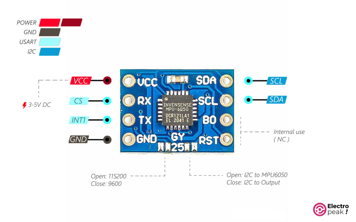
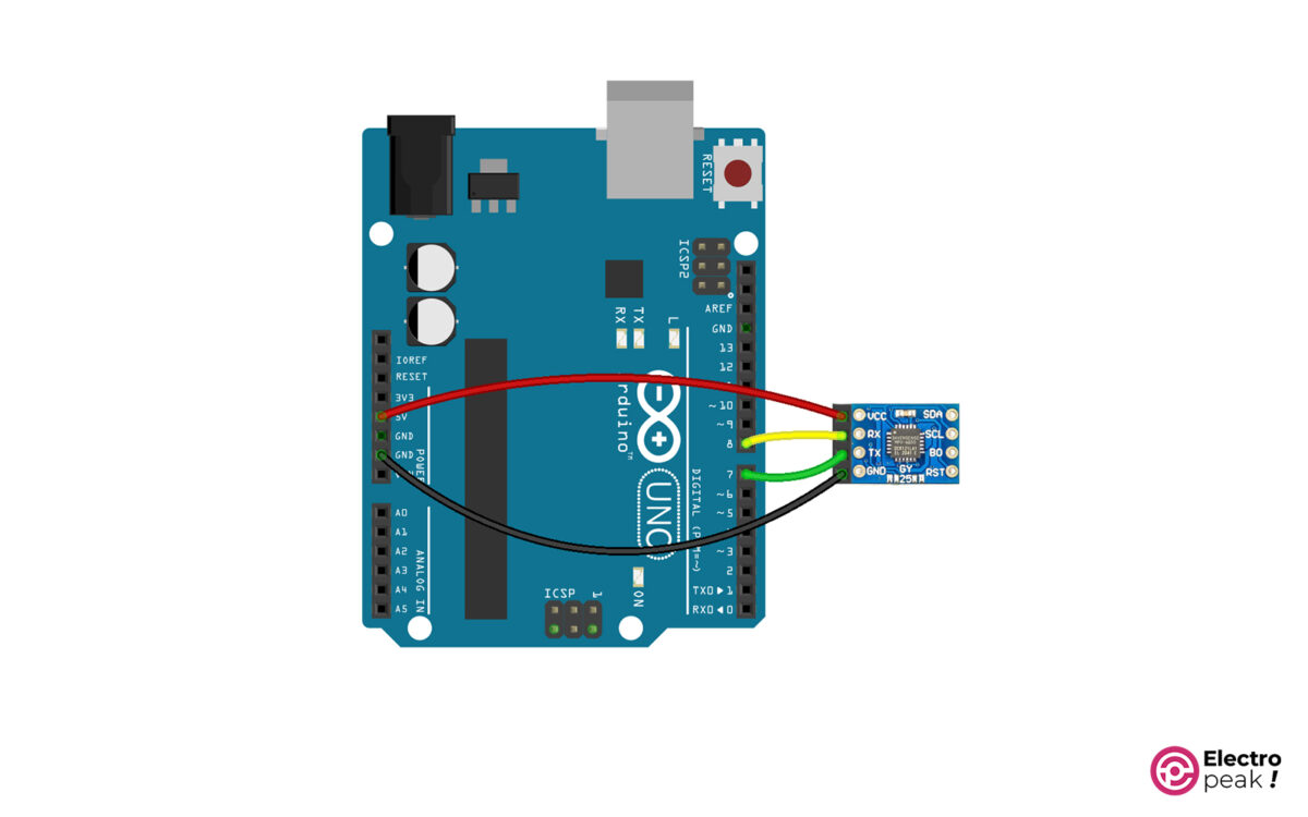
 * connect sensor TX to arduino RX(in this code pin #8) 
 * connect sensor RX to arduino TX(in this code pin #7)
 */
#include <SoftwareSerial.h> // software Serial, to use another pins as TX, RX
static const int RXPin = 7, TXPin = 8; // announce your Rx and Tx pins
SoftwareSerial newserial(RXPin, TXPin);
float Roll,Pitch,Yaw;
unsigned char Re_buf[8],counter=0;

void setup()
{ 
Serial.begin(9600);
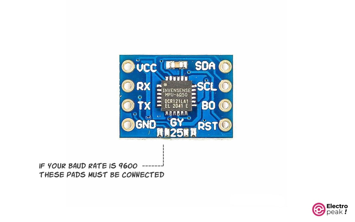
newserial.begin(115200); // SoftwareSerial can only support 9600 baud rate for GY-25 but Serial3 can support 115200 and 9600 both
delay(4000); 
newserial.write(0XA5); 
newserial.write(0X54);//correction mode
delay(4000);
newserial.write(0XA5); 
newserial.write(0X51);//0X51:query mode, return directly to the angle value, to be sent each read, 0X52:Automatic mode,send a direct return angle, only initialization 
}
//looooooooooooooooooop
void loop() {
if (newserial.available()) { 
serialEvent();
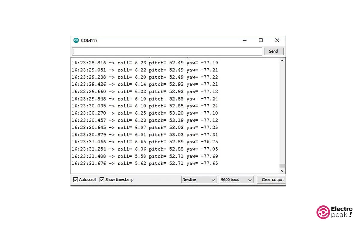
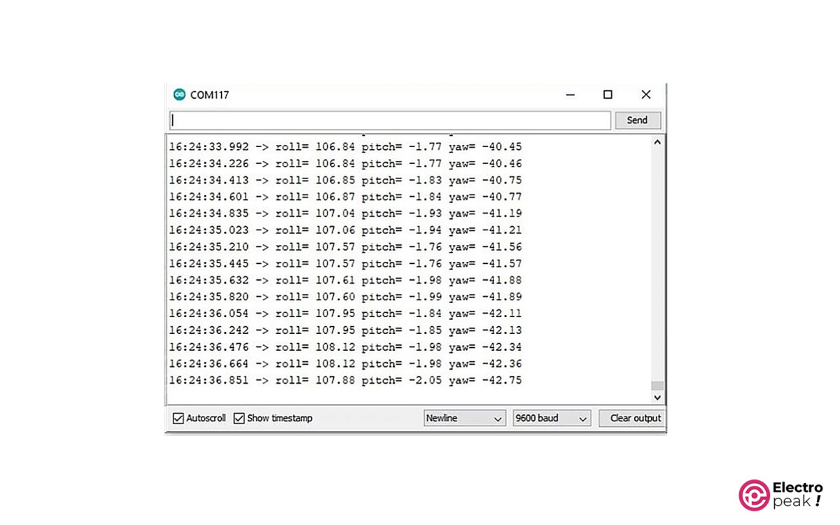
Serial.print("roll= ");
Serial.print(Roll);
Serial.print(" pitch= "); 
Serial.print(Pitch);
Serial.print(" yaw= "); 
Serial.println(Yaw);
}
else Serial.println("check connections");
delay(200);
}
//loooooooooooooooooooop END
//data reading function
void serialEvent() { 
 newserial.write(0XA5); 
 newserial.write(0X51);//send it for each read
 while (newserial.available()) { 
 Re_buf[counter]=(unsigned char)newserial.read();
 if(counter==0&&Re_buf[0]!=0xAA) return; 
 counter++; 
 if(counter==8) { // package is complete 
 counter=0; 
 if(Re_buf[0]==0xAA && Re_buf[7]==0x55) { // data package is correct 
 Yaw=(int16_t)(Re_buf[1]<<8|Re_buf[2])/100.00; 
 Pitch=(int16_t)(Re_buf[3]<<8|Re_buf[4])/100.00;
 Roll=(int16_t)(Re_buf[5]<<8|Re_buf[6])/100.00;
 } 
 } 
 } 
}

The output should look like the image below. You should also see different numbers when changing the sensor angle.

Liked What You See?​
Get Updates And Learn From The Best​

Leave a Reply

Your email address will not be published. Required fields are marked *