Interfacing EMG Muscular Signal Sensor with Arduino
Written by
Amir Mohammad Shojaei
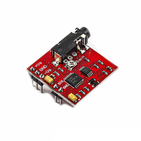
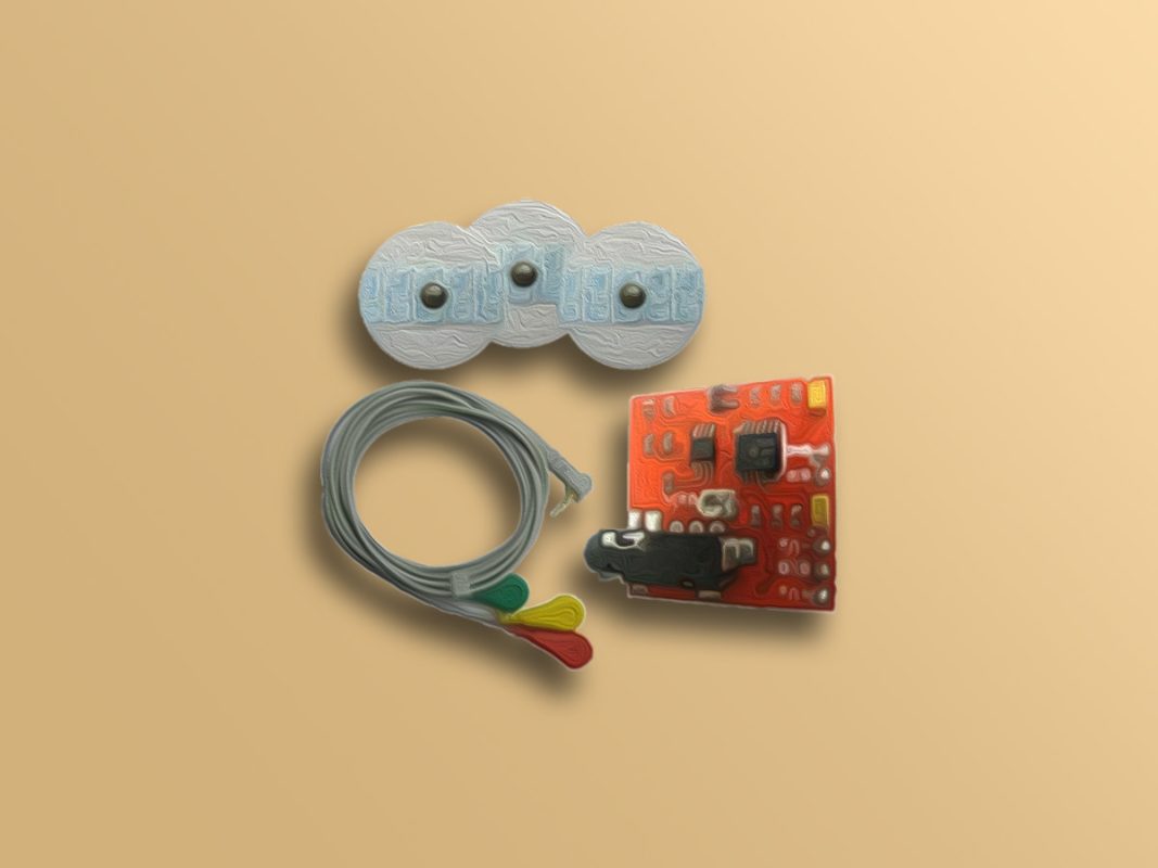
EMG Muscular Signal Sensor Features
In medical research, measuring the activity, contraction and expansion of muscles is important. The EMG muscle sensor measures the muscle activity and produces a signal to show the amount of expansion and contraction. Therefore, the output depends on the amount of activity in the selected muscle. 3 Green, red and yellow electrodes connect to the module for transmitting electrical signals from the muscle motion.
Features:
Small Form Factor
Specially Designed for Microcontrollers
Adjustable Gain using onboard potentiometer
5mm Connector
Applications:
Video games
Robotics
Medical equipment
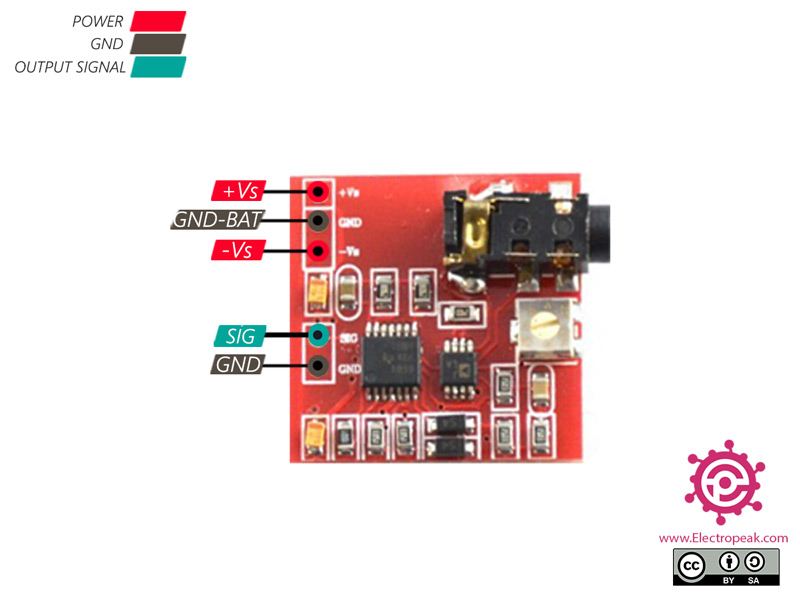
EMG Muscular Signal Sensor Pinout
This module has 5 pins:
Vs+: Positive power supply
GND-BAT: Ground Battery
Vs-: Negative power supply
SIG: Analog output
GND: Ground
You can see the pinout of this module here.
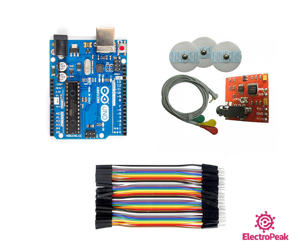
Required Material
Hardware component
Arduino UNO R3
×
1
EMG Muscular Signal Sensor
×
1
Male to Female jumper wire
×
1
Software Apps
Arduino IDE
Interfacing EMG Muscular Signal Sensor with Arduino
Step 1: Circuit
Electrode Connection:
The three electrodes are used to transmit muscle signals. Each electrode must be in the proper position for better function.
Once you have decided which muscle to monitor, connect them as follows:
Green electrode: Place this electrode on the middle of the desired muscle
Red electrode: Place this electrode at the end of the desired muscle.
Yellow electrode: Place the last electrode on a bony or non-muscular part of the body near to the desired muscle.
For example, to evaluate the forearm muscle, you can place electrodes on your hand as follows:
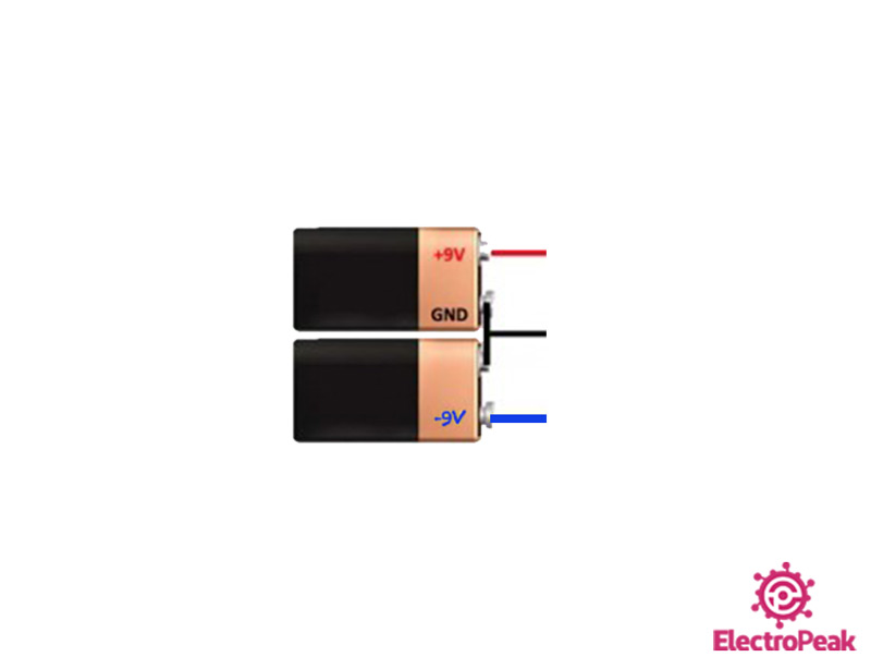
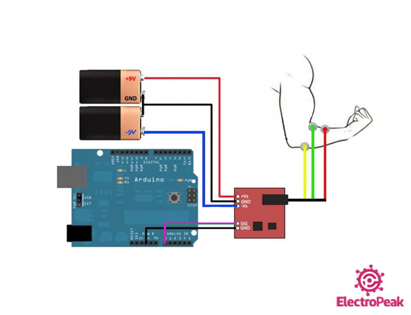
Power Supply Connection:
We use two power supplies or batteries to generate +Vs and -Vs. First connect the negative side of first battery to positive side of second battery, as shown below. This creates an electric ground for power supply.
So, the positive side of first battery becomes +Vs and the negative end of the second battery becomes -Vs.
The following circuit shows how you should connect Arduino to EMG sensor. Connect wires accordingly.
Step 2: Code
Upload the following code to Arduino.
/*
EMG-Muscular-Signal-Sensor
made on 26 Jan 2021
by Amir Mohammad Shojaee @ Electropeak
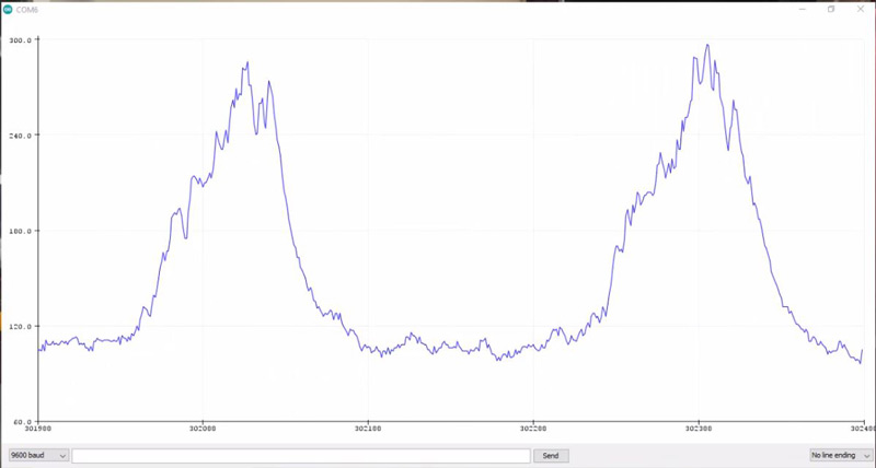
We want to observe the changes in analog output signal of the module as the forearm muscle expands and contracts. To do this, open the Serial Plotter and see the output signal.
Hi.
could you please share your C code with us? I will help you better if I know how to Setup this sensor
any way. could you please try with below C Code
void setup() {
// initialize serial communication at 115200 bits per second:
Serial.begin(115200);
//set the resolution to 12 bits (0-4096)
analogReadResolution(12);
}
void loop() {
// read the analog / millivolts value for pin 2:
int analogValue = analogRead(2);
int analogVolts = analogReadMilliVolts(2);
// print out the values you read:
Serial.printf(“ADC analog value = %d\n”,analogValue);
Serial.printf(“ADC millivolts value = %d\n”,analogVolts);
delay(100); // delay in between reads for clear read from serial
}
Hey! I’m not seeing any change in the serial plotter, it only goes up and down between 110 and 111. What am I doing wrong? I’m using an Arduino Nano and the same EMG and the image. I have also uploaded that same code. What other things should I be careful about?
Hi, I followed the steps but my arduino receives a signal jumping between 71 and 72, it doesn’t matter if I contract my muscles or not. Is there a possible fix?
Hello! i made this circuit but with alternative version of the PCB where there is no potentiometer , but when i plug everthing it just go to value aroun 75 +-2 and stays there without reactiong to contraction. Is there a way to check where is the problem or how to check if electrodes are transmiting any signal
Hi Mihail,
you can use an external potentiometer multi turn to see if there is a change in your output.
Also, the output signal is too small to be seen on oscilloscope.
In that case, stoke in your board and fine-tune it.
The EMG sensor is a highly sensitive module. I recommend carefully following all the steps outlined in the article. Pay close attention to the power supply (using two batteries) and the correct placement of the pads on the body, as these are crucial for proper functionality.
hi, this works for me without the 9v batteries and just plugging into 3.3v in my arduino mega. I am just wondering what is the purpose of the 9v batteries then if it seems to work without?
Hello Mary,
Based on the schematic of this module, we note that it includes the AD8221 and TL084 components. According to the datasheets:
– First IC: Requires a power supply of ±2.3 V to ±18 V.
– Second IC: Requires a power supply of ±3 V to ±18 V.
For accurate readings, both positive and negative voltage are necessary because EMG pulse signals naturally have both positive and negative values.
The Arduino’s 3.3V line is only suitable as a voltage reference and does not provide enough current to power the module. Additionally, the circuit lacks dedicated positive and negative voltage lines.
To create a simple and stable ± voltage for this setup, we suggest using two batteries as described in the referenced article. This will meet the voltage requirements and ensure reliable performance.
Hi,
You can use two Li-ion batteries like a 9V battery to create ±4.2V, but this may introduce some noise.
For better stability, use four Li-ion batteries—two for positive and two for negative—to get ±8.4V.
Alternatively, you can use a boost regulator to step up to 9V and an inverting boost converter to generate -9V.
If you have around 12V available, use a DC-DC Step Down Power Supply Module Positive and Negative 1A -Buck Converter can provide stable positive and negative voltage.
Hello, I truly need your help.
I did everything as indicated in this tutorial and tried with several sEMG sensor (the model without the potentiometer onboard) and the signal acquired by the arduino board is always oscillating around a constant (290 +-5 V or 5+-5V) no matter the contraction of the muscle. I also noticed that the sensor didn’t seems to detect the electrode as the output was similar with unpluging the red green and yellow cable from the electrode. Do you have any idea of where does the problem come from?
I’m facing problem with threshold adjustment for the same EMG sensor, every time I used it there is a sudden change in the EMG values and I have to change the threshold value every time. I was recommended to add potentiometer before EMG sensor but I don’t know how to connect that properly. Can someone tell me how to do that or is it solve the following problem


Comments (24)
i want arduino code of feature extraction for emg signal pleeez!
note: i use above sensor muscle sensor V3 (outputs filtred ,rectfired signal)
Hi.
That seems to be a highly complicated job and out of the context of this tutorial.
Hello! Can the EMG sensor be connected to arduino protoboard 5V external power supply instead of 9V battery?
Hi.
Unfortunately not! This module needs around 9 volts to operate. It also requires -9 volts, which makes us use two 9V batteries.
My output of emg sensor is zero.. If I disconnected any electrode from body it will be 1023.why is that?
Hi.
could you please share your C code with us? I will help you better if I know how to Setup this sensor
any way. could you please try with below C Code
void setup() {
// initialize serial communication at 115200 bits per second:
Serial.begin(115200);
//set the resolution to 12 bits (0-4096)
analogReadResolution(12);
}
void loop() {
// read the analog / millivolts value for pin 2:
int analogValue = analogRead(2);
int analogVolts = analogReadMilliVolts(2);
// print out the values you read:
Serial.printf(“ADC analog value = %d\n”,analogValue);
Serial.printf(“ADC millivolts value = %d\n”,analogVolts);
delay(100); // delay in between reads for clear read from serial
}
#include
int emgPin = A0;
int servoPin = 7;
Servo servo;
int emgThreshold = 20; // Adjust this threshold as needed
float emgFiltered = 0.0; // Filtered EMG value
float alpha = 0.2; // Filter coefficient
void setup() {
Serial.begin(9600);
servo.attach(servoPin);
void loop() {
int emgValue = analogRead(emgPin);
// Apply the low-pass filter
emgFiltered = (alpha * emgValue) + ((1 – alpha) * emgFiltered);
if (emgFiltered > emgThreshold) {
servo.write(120); //Change servo position acc. to your requirement
} else {
servo.write(30);
}
Serial.print(“EMG Value: “);
Serial.println(emgFiltered);
delay(50); // Adjust the delay as needed
}
Hey! I’m not seeing any change in the serial plotter, it only goes up and down between 110 and 111. What am I doing wrong? I’m using an Arduino Nano and the same EMG and the image. I have also uploaded that same code. What other things should I be careful about?
Hi, I followed the steps but my arduino receives a signal jumping between 71 and 72, it doesn’t matter if I contract my muscles or not. Is there a possible fix?
Hi
please make sure that you use right analog channel to read measurment
change your analog channel or check your wiring
Hi can i ask,l few things?
1. what is the exact name for the emg sensor?
2. If there is no exact name, can you provide the exact details which includes block diagram and working principles for me to refer?
Hi Haiqal,
The code of ICs on the module is available in the product images. You can check them out in the link below
EMG Muscular Signal Sensor
Hi! Is it possible if i want to make a signal classification using ML that will be processed in a microcontroller/single board computer?
Hello! i made this circuit but with alternative version of the PCB where there is no potentiometer , but when i plug everthing it just go to value aroun 75 +-2 and stays there without reactiong to contraction. Is there a way to check where is the problem or how to check if electrodes are transmiting any signal
Hi Mihail,
you can use an external potentiometer multi turn to see if there is a change in your output.
Also, the output signal is too small to be seen on oscilloscope.
In that case, stoke in your board and fine-tune it.
signal stuck to 0 what could be the problem?
Hi Nick,
The EMG sensor is a highly sensitive module. I recommend carefully following all the steps outlined in the article. Pay close attention to the power supply (using two batteries) and the correct placement of the pads on the body, as these are crucial for proper functionality.
hi, this works for me without the 9v batteries and just plugging into 3.3v in my arduino mega. I am just wondering what is the purpose of the 9v batteries then if it seems to work without?
Hello Mary,
Based on the schematic of this module, we note that it includes the AD8221 and TL084 components. According to the datasheets:
– First IC: Requires a power supply of ±2.3 V to ±18 V.
– Second IC: Requires a power supply of ±3 V to ±18 V.
For accurate readings, both positive and negative voltage are necessary because EMG pulse signals naturally have both positive and negative values.
The Arduino’s 3.3V line is only suitable as a voltage reference and does not provide enough current to power the module. Additionally, the circuit lacks dedicated positive and negative voltage lines.
To create a simple and stable ± voltage for this setup, we suggest using two batteries as described in the referenced article. This will meet the voltage requirements and ensure reliable performance.
Hello, is it possible to power this module without using 9V batteries? I nead to power it using 18650 LiIon-battery.
Hi,
You can use two Li-ion batteries like a 9V battery to create ±4.2V, but this may introduce some noise.
For better stability, use four Li-ion batteries—two for positive and two for negative—to get ±8.4V.
Alternatively, you can use a boost regulator to step up to 9V and an inverting boost converter to generate -9V.
If you have around 12V available, use a DC-DC Step Down Power Supply Module Positive and Negative 1A -Buck Converter can provide stable positive and negative voltage.
Hello, I truly need your help.
I did everything as indicated in this tutorial and tried with several sEMG sensor (the model without the potentiometer onboard) and the signal acquired by the arduino board is always oscillating around a constant (290 +-5 V or 5+-5V) no matter the contraction of the muscle. I also noticed that the sensor didn’t seems to detect the electrode as the output was similar with unpluging the red green and yellow cable from the electrode. Do you have any idea of where does the problem come from?
I’m facing problem with threshold adjustment for the same EMG sensor, every time I used it there is a sudden change in the EMG values and I have to change the threshold value every time. I was recommended to add potentiometer before EMG sensor but I don’t know how to connect that properly. Can someone tell me how to do that or is it solve the following problem
How can I run a game with it?