Dual-Axis Joystick Shield Features
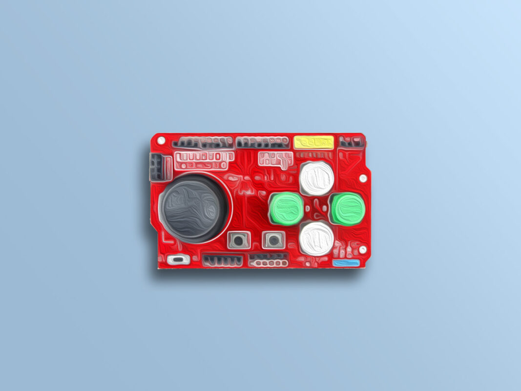
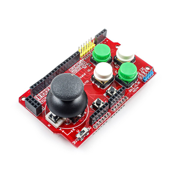
The dual-axis joystick shield is commonly used in robotics and game consoles. This module includes a 2-Axis joystick, 4 large buttons, 2 small buttons and a number of pins to connect to other components.
The key features of this joystick are:
- A joystick in both X and Y directions
- 4 buttons with plastic cover in 4 different directions
- 2 separate small buttons
- Serial / Bluetooth interface
- I2C interface
- nRF24L01 interface
- Connection pins to nRF24L01 module
- Nokia 5110 LCD interface
- Interface connector
- Power switch to switch between 3.3 and 5V
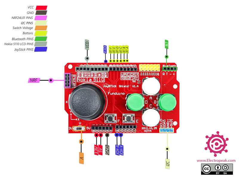
Dual-Axis Joystick Shield for Arduino Pinout
This shield has different parts to interface as follows:
Joystick connections:
- JOY-X: Joystatic x-axis – connected to A0
- JOY-Y: Joystatic y axis – connected to A1
- JOY-K: Joystick switch – connected to D8
Power supply connections:
- V: Set to 5V to connect to the Arduino Uno board and 3.3V to connect to Arduino boards with 3.3V power supply such as Due.
Button connections:
- BT-A: Button A – Connected to D2
- BT-B: Button A – Connected to D3
- BT-C: Button A – Connected to D4
- BT-D: Button A – Connected to D5
- BT-E: Button A – Connected to D6
- BT-F: Button A – Connected to D7
Bluetooth pin connections:
- BLT: Includes 4 pins to connect to Bluetooth
I2C connections:
- I2C: Includes SDA and SCL pins – connected to A4 and A5
Pin connections nRF24L01:
- NRF: this module has 9 pins:
CE: Connected to D9
CSN: Connected to D10
SCK: Connected to D13
MOSI: Connected to D11
MISO: Connected to D12
IRQ: Base without connection
GND: Ground
VCC: Connected to 3.3 V
Nokia 5110 LCD pin connectors:
- LCD: Connected to pins D9 to D13
Note
You will not be able to use both the nRF24L01 and Nokia 5110 LCD modules at the same time due to interference between pins.
Other connections:
- GND: Ground
- 5V: Power supply – 5V
- 3.3V: Power supply 3.3V
You can see the pinout of this module in the image below.
Required Materials
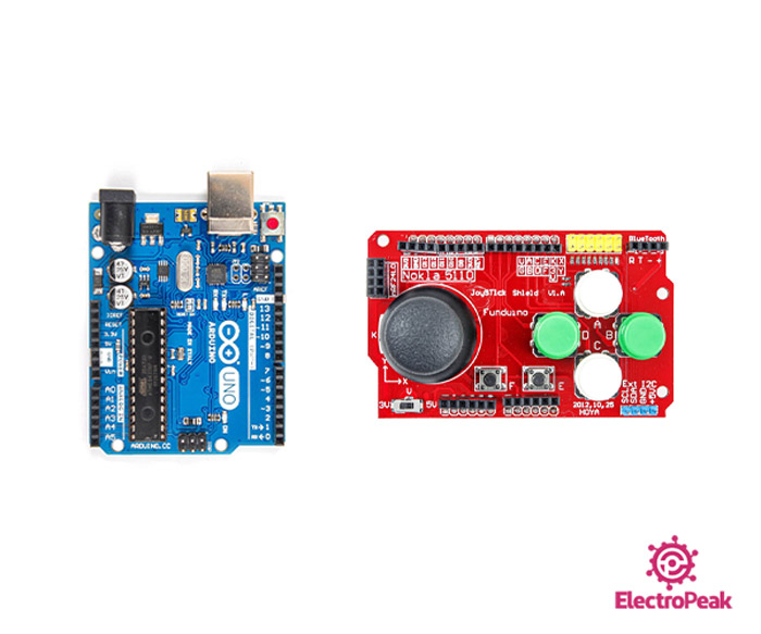
Hardware Components
Software Apps
Interfacing Dual-Axis Joystick Shield with Arduino
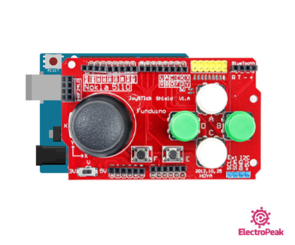
Step 1: Circuit
Place the shield on Arduino as shown below.
Step 2: Code
Upload the following code to Arduino.
    /*
  Dual-Axis-Joystick-Shield
  made on 16 Nov 2020
  by Amir Mohammad Shojaee @ Electropeak
  Home

*/

# define UP 2
# define RIGHT 3
# define DOWN 4
# define LEFT 5
# define E 6
# define F 7
# define Joy_BT 8
# define Joy_X A0
# define Joy_Y A1
 int bottons[]={UP,RIGHT,DOWN,LEFT,E,F,Joy_BT};

void setup(){
  for(int i=0;i<7;i++) pinMode(bottons[i],INPUT);
  Serial.begin(9600);
}

void loop(){
  Serial.print("UP:");Serial.print(digitalRead(UP));
  Serial.print("  RIGHT:");Serial.print(digitalRead(RIGHT));
  Serial.print("  DOWN:");Serial.print(digitalRead(DOWN));
  Serial.print("  LEFT:");Serial.print(digitalRead(LEFT));
  Serial.print("  E:");Serial.print(digitalRead(E));
  Serial.print("  F:");Serial.print(digitalRead(F));
  Serial.print("  Joy_BT:");Serial.print(digitalRead(Joy_BT));

  Serial.print("  Joy_X:");Serial.print(analogRead(Joy_X));
  Serial.print("  Joy_Y:");Serial.println(analogRead(Joy_Y));

  delay(500);
}
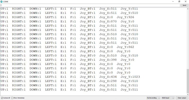
In this code, you can see how this module works. Switching keys and directions of X and Y are shown in the Serial Monitor.
Note
Note that the keys are in the Pull-Up state and will be zero by pressing.
The output is as follows. As you can see, the keys and joystick are accidentally pressed.