
DS1307 RTC Module Features
The DS1307 real time clock module can be used for keeping date in different projects. This RTC module provides seconds, minutes, hours, day, date, month, and year information. In this module, the date is set automatically based on whether the month is 29, 30 or 31 days, and also whether it is leap year or not. This RTC module can communicate with different microcontrollers using the I2C communication protocol.
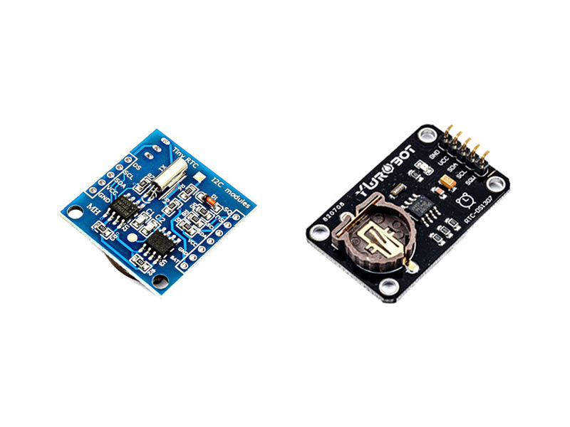
The DS1307 RTC module is available on the market in two different versions.
Note
In the image above that shows the two types of the DS1307 RTC module, the one on the left comes with an internal 24C32 EEPROM memory. This can be used to store settings and also has I2C communication protocol.
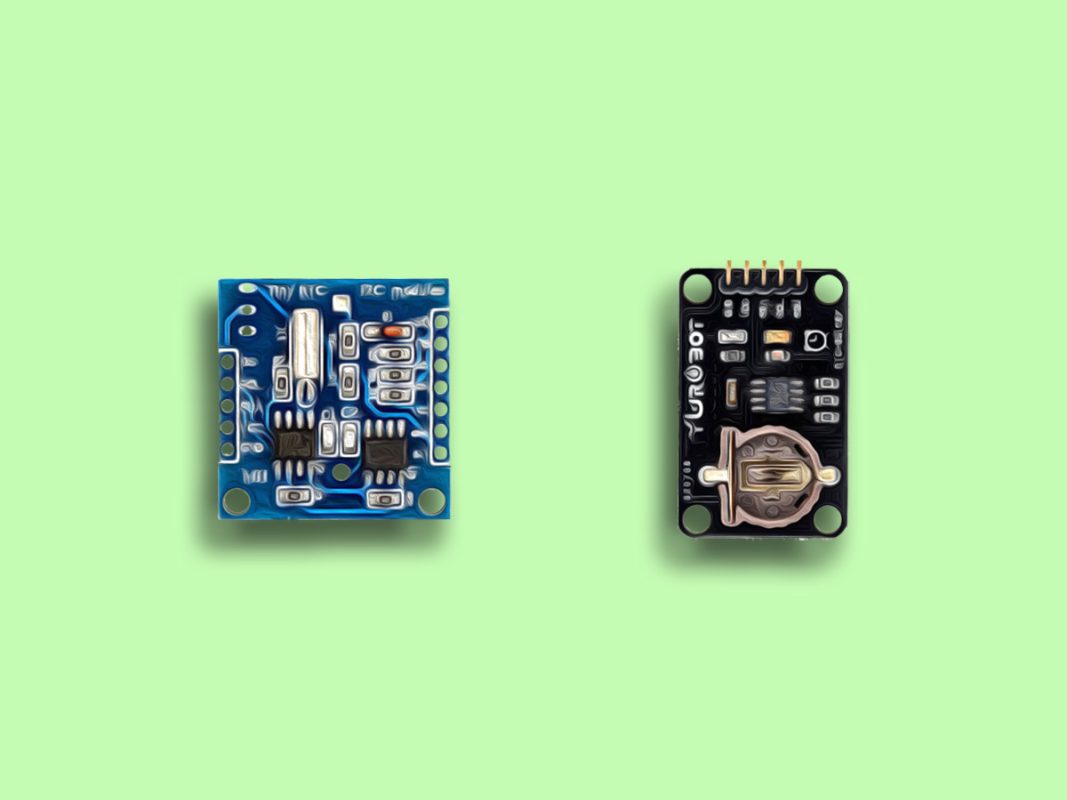
The module also has a section for soldering the DS18B20 temperature sensor, which can be used if needed. Its location is indicated by a red box in the figure below:

Note
In the image that shows the two types of the DS1307 RTC module, the one on the right has an adjustable square wave output.
DS1307 RTC Module Pinout
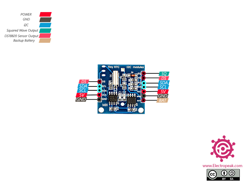
One of the two versions of this module has 12 pins:
5 pins on one side for DS1307 communications:
- DS: DS18B20 temperature sensor output
- SCL: Serial Clock Input for I2C protocol
- SDA: Serial Data Input / Output for I2C protocol
- VCC: Module power supply – 5V
- GND: Ground
7 other pins on the other side to 24C32 EEPROM communications:
- SQ: Output square wave
- DS: DS18B20 temperature sensor output
- SCL: Serial Clock Input for I2C protocol
- SDA: Serial Data Input / Output for I2C protocol
- VCC: Module power supply – 5V
- GND: Ground
- BAT: Backup battery
Note
Both I2C and power supply pins on both sides are the same and no need to connect to Arduino in order to communicate with memory and clock. This means that by connecting one side to Arduino, you can connect to both DS1307 and 24C32 EEPROM. The DS pin is also the same on both sides.
You can see the pinout of this module in the image below.
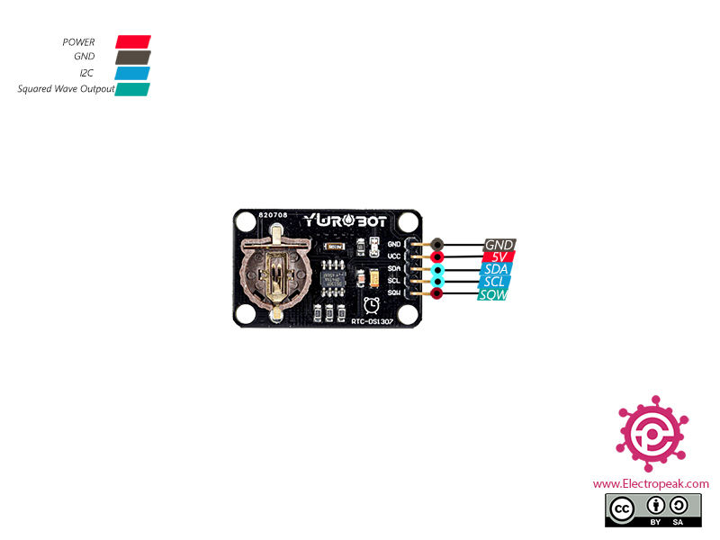
The other type of the DS1307 module has 5 pins:
- GND: Ground
- VCC: Module power supply – 5V
- SDA: Serial Data Input / Output for I2C protocol
- SCL: Serial Clock Input for I2C protocol
- SQW: Square wave output
You can see the pinout of this module in the image below.
Required Materials
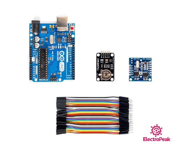
Hardware Components
Software Apps
Interfacing DS1307 RTC Module with Arduino
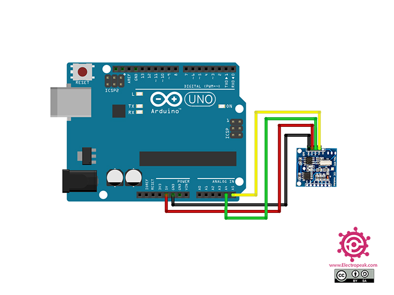
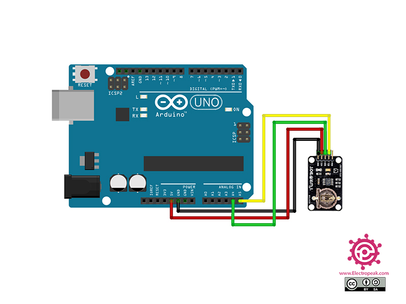
Step 1: Circuit
The following circuits show how you should connect Arduino to the DS1307 modules. Connect wires accordingly
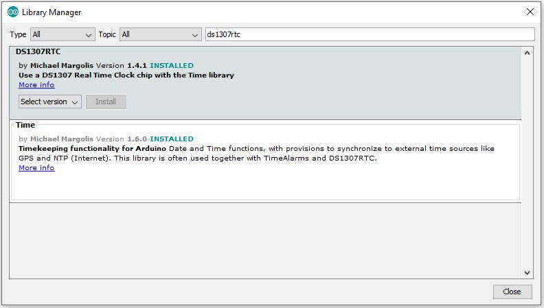
Step 2: Installing Library
From this part, everything is the same for both versions of the DS1307 RTC module. Go to “Library Manager” and install the DS1307RTC library.
Tip
If you need more help with installing a library on Arduino, read this tutorial: How to Install an Arduino Library
Step 3: Code
Upload the following code to Arduino. After that, open Serial Monitor.
   /*
Modified on Nov 24, 2020
Modified by MehranMaleki from Arduino Examples
Home
*/


#include <Wire.h>
#include <DS1307RTC.h>


const char *monthName[12] = {
  "Jan", "Feb", "Mar", "Apr", "May", "Jun",
  "Jul", "Aug", "Sep", "Oct", "Nov", "Dec"
};
tmElements_t tm;


void setup() {
  Serial.begin(9600);
  while (!Serial) ; // wait for serial
  delay(200);


  bool parse=false;
  bool config=false;

  // get the date and time the compiler was run
  if (getDate(__DATE__) && getTime(__TIME__)) {
    parse = true;
    // and configure the RTC with this info
    if (RTC.write(tm)) {
      config = true;
    }
  }

  if (parse && config) {
    Serial.print("DS1307 configured Time=");
    Serial.print(__TIME__);
    Serial.print(", Date=");
    Serial.println(__DATE__);
  } else if (parse) {
    Serial.println("DS1307 Communication Error :-{");
    Serial.println("Please check your circuitry");
  } else {
    Serial.print("Could not parse info from the compiler, Time=\"");
    Serial.print(__TIME__);
    Serial.print("\", Date=\"");
    Serial.print(__DATE__);
    Serial.println("\"");
  }
}


void loop() {

  if (RTC.read(tm)) {
    Serial.print("Ok, Time = ");
    print2digits(tm.Hour);
    Serial.write(':');
    print2digits(tm.Minute);
    Serial.write(':');
    print2digits(tm.Second);
    Serial.print(", Date (D/M/Y) = ");
    Serial.print(tm.Day);
    Serial.write('/');
    Serial.print(tm.Month);
    Serial.write('/');
    Serial.print(tmYearToCalendar(tm.Year));
    Serial.println();
  } else {
    if (RTC.chipPresent()) {
      Serial.println("The DS1307 is stopped.  Please run the SetTime");
      Serial.println("example to initialize the time and begin running.");
      Serial.println();
    } else {
      Serial.println("DS1307 read error!  Please check the circuitry.");
      Serial.println();
    }
    delay(9000);
  }
  delay(1000);
}


void print2digits(int number) {
  if (number >= 0 && number < 10) {
    Serial.write('0');
  }
  Serial.print(number);
}


bool getTime(const char *str)
{
  int Hour, Min, Sec;

  if (sscanf(str, "%d:%d:%d", &Hour, &Min, &Sec) != 3) return false;
  tm.Hour = Hour;
  tm.Minute = Min;
  tm.Second = Sec;
  return true;
}


bool getDate(const char *str)
{
  char Month[12];
  int Day, Year;
  uint8_t monthIndex;

  if (sscanf(str, "%s %d %d", Month, &Day, &Year) != 3) return false;
  for (monthIndex = 0; monthIndex < 12; monthIndex++) {
    if (strcmp(Month, monthName[monthIndex]) == 0) break;
  }
  if (monthIndex >= 12) return false;
  tm.Day = Day;
  tm.Month = monthIndex + 1;
  tm.Year = CalendarYrToTm(Year);
  return true;
}
In this code, at first, the time is given to the module as the starting point. Then the module starts working, and the updated time appears on Serial Monitor every second.
The output is as follows.

