Interfacing APC220 RF Transceiver Module with Arduino
Written by
Mohammad Damirchi
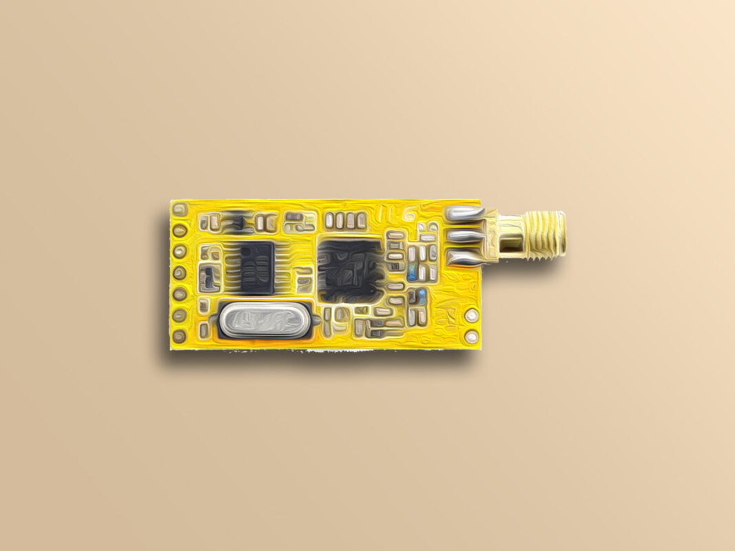
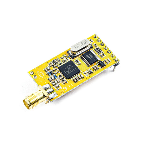
APC220 Wireless Data Communication Module Features
Electronic devices need to be connected wirelessly in so many cases. In these cases, Radio Frequency or RF equipments are used. RF modules include all radio waves that can travel different distances and reach the receiver according to their frequency and amplitude.
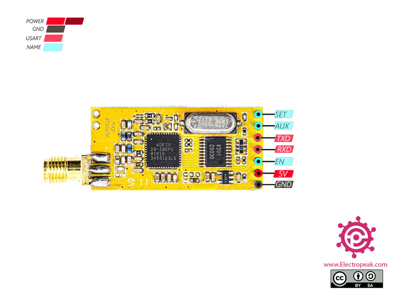
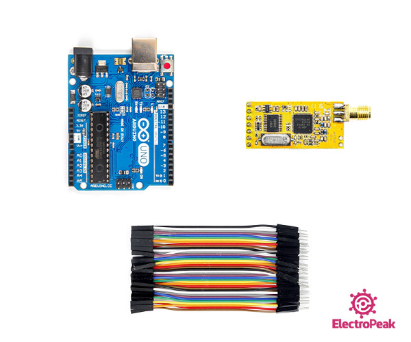
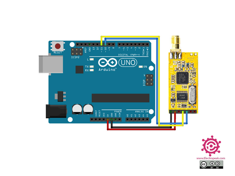
The APC220 module uses UART / TTL for communication. This module comes with a USB to TTL converter that you can use to connect the module directly to your system and connect the second module to a microcontroller. This module offers a wide range for communication over long distances, so, it is recommended to use in robots.
*/
#include <SoftwareSerial.h>
SoftwareSerial mySerial(10, 11); // RX, TX
void setup() {
// Open serial communications and wait for port to open:
Serial.begin(9600);
while (!Serial) {
; // wait for serial port to connect. Needed for native USB port only
}
// set the data rate for the SoftwareSerial port
mySerial.begin(9600);
}
void loop() { // run over and over
if (mySerial.available()) {
Serial.write(mySerial.read());
}
if (Serial.available()) {
mySerial.write(Serial.read());
}
}
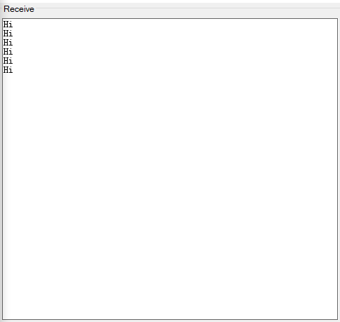
This code is for testing the connection between the Arduino and your system.
Now open the serial monitors of the Arduino IDE and the converter. By sending data on each side, you can observe the data on the other side.
Note
The Serial Monitor baud rate is 9600 on both sides by default.