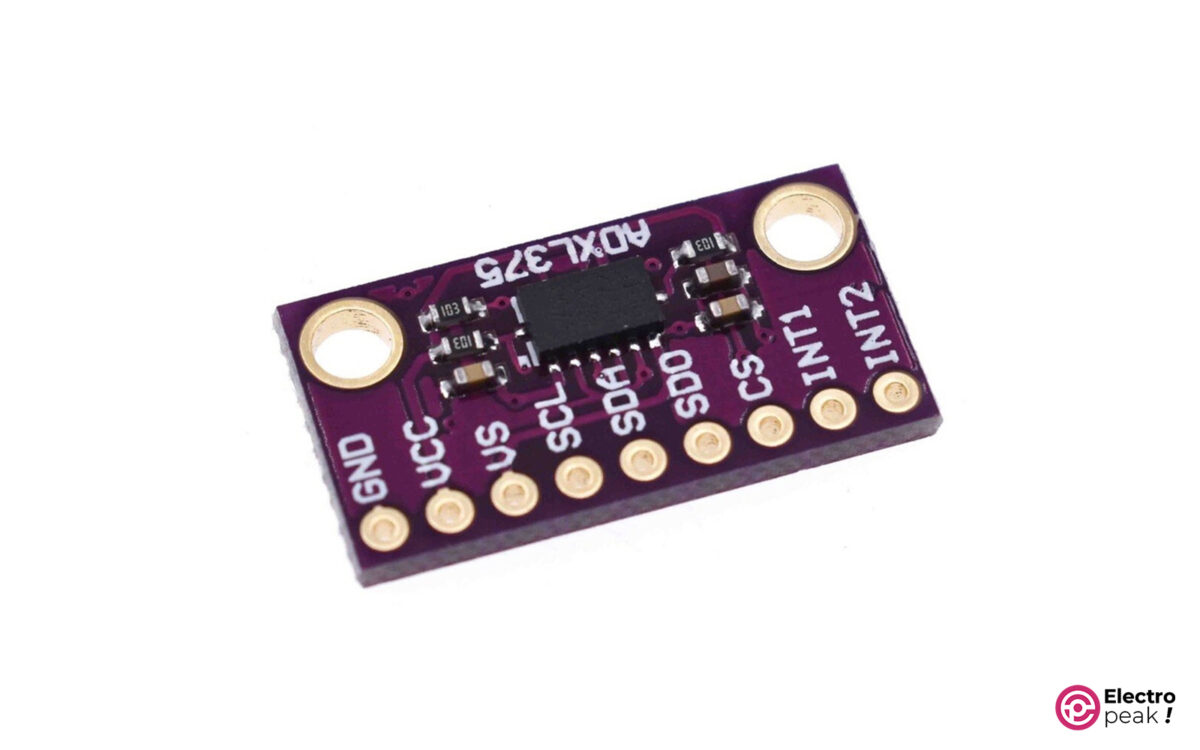
What is ADXL375 Accelerometer Module?
The ADXL375 module is an ultra-accurate 3-axis accelerometer sensor. This accelerometer can measure up to 200 g of force in three axes (X Y Z) (g: the gravity acceleration, which is around 9.8 meters per square second. In simpler words: nearby the acceleration of a spaceship rocket!!!)
Other useful features: I2C and SPI interfaces for communication as well as two interrupt pins that can be configured independently.
ADXL375 is an advanced version of ADXL345 and ADXL343 sensors, which have almost the same performance. The difference is that the measuring range for ADXL345 and ADXL343 modules is ±16g and adjustable, but it has increased by 200g for the 375 models, and cannot be changed.
ADXL375 Accelerometer Module Features
- Low power; 35 µA in measurement mode and 0.1 µA in standby mode (when Vs=2.5v)
- Shock detection
- Working voltage range: 2 to 3.6V
- I/O Voltage range: 1.7V to Vs
- SPI (3- or 4-wire) and I2C communication ports
- Dimension: 3mm*5mm*1mm
- For more information, I strongly recommend you read the module datasheet.
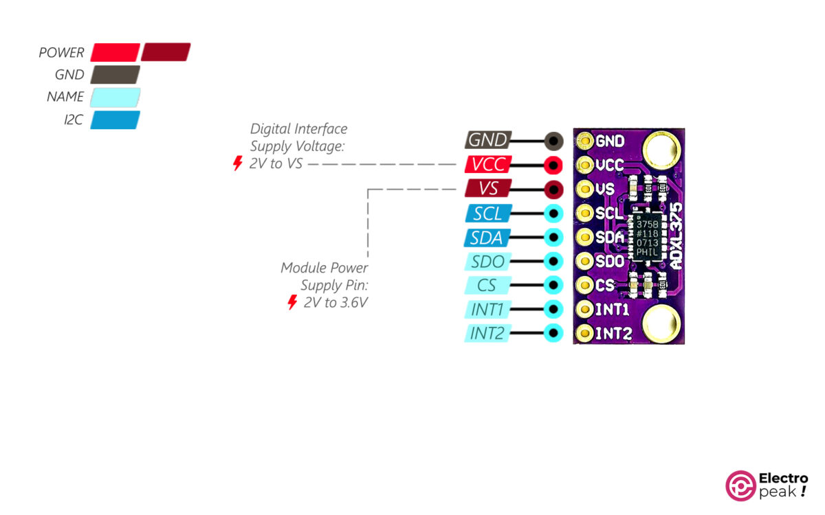
ADXL375 Accelerometer Pinout
The ADXL375 module has 9 pins:
- GND: Ground
- VCC: Digital Interface Supply Voltage (2 to Vs)
- VS: Supply Voltage (2 to 3.6v)
- SCL/SCLK: I2C Serial Communications Clock (SCL)/SPI Serial Communications Clock (SCLK).
- SDA/SDI/SDIO: I2C Serial Data (SDA)/SPI 4-Wire Serial Data Input (SDI)/SPI 3-Wire Serial Data Input and Output (SDIO).
- SDO/ALT ADDRESS: SPI 4-Wire Serial Data Output (SDO)/I2C Alternate Address Select (ALT ADDRESS).
- CS: Chip Select
- INT1: Interrupt 1 Output
- INT2: Interrupt 2 Output
You can see the module pinout in the image below.
Required Materials

Hardware Components
Software
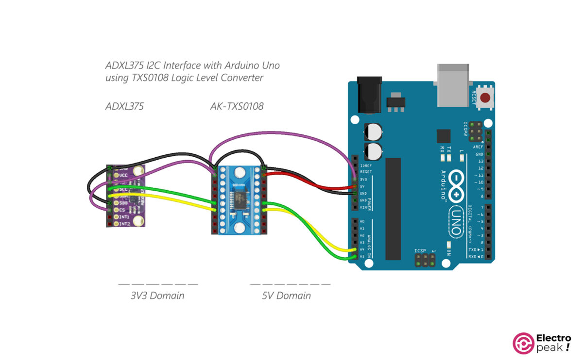
Interfacing ADXL375 Sensor with Arduino (I2C Mode)
Step 1: Wiring
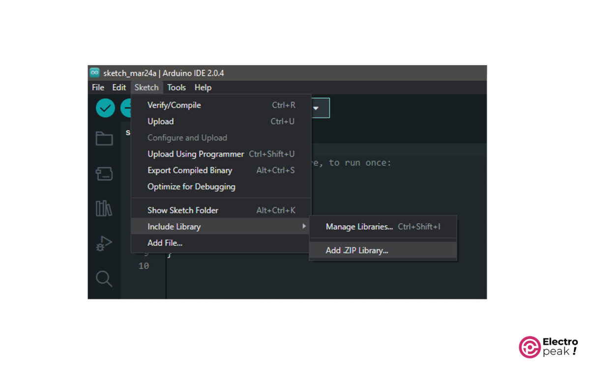
Step 2: Library
Download the libraries from the links below. Then select and add the downloaded file from SKETCH>Include Library>Add .ZIP Library.
- Adafruit_ADXL375 library: written to work with this module.
ADAFRUIT_ADXL375 library zip file
- Adafruit_Sensor library: required for the above library.
ADAFRUIT_SENSOR library zip file
- Wire library: for I2C communication.
If you need help installing the libraries and new boards in Arduino IDE Software, you can visit this link.
Step 3: Code
Copy the following code into Arduino IDE. After uploading the code, open the serial monitor window.
/*this is originaly adafruit_adxl375 library example,
 * we just modified the code for i2c interface.
 * electropeak.com , Ali Akbar Hosseini
 * adxl375 i2c test, pin connection are as below for i2c protocol
ADXL375 cs-->Vcc(3.3v),
ADXL375 SDO--->gnd,
ADXL375 Vs--->vcc-->3.3v,
ADXL375 SCL---<logic level convertor>---Arduino SCL(A5),
ADXL375 SDA---<logic level convertor>---Arduino SDA(A4)
*/
#include <Wire.h>
#include <Adafruit_Sensor.h>
#include <Adafruit_ADXL375.h>
//-----------------------for spi interface, define the spi pins
//#define ADXL375_SCK 13
//#define ADXL375_MISO 12
//#define ADXL375_MOSI 11
//#define ADXL375_CS 10

Adafruit_ADXL375 accel = Adafruit_ADXL375(12345);
/* Uncomment for software SPI */
//Adafruit_ADXL375 accel = Adafruit_ADXL375(ADXL375_SCK, ADXL375_MISO, ADXL375_MOSI, ADXL375_CS, 12345);
/* Uncomment for hardware SPI */
//Adafruit_ADXL375 accel = Adafruit_ADXL375(ADXL375_CS, &SPI, 12345);

void displayDataRate(void)
{
 Serial.print ("Data Rate: ");

 switch(accel.getDataRate())
 {
 case ADXL343_DATARATE_3200_HZ:
 Serial.print ("3200 ");
 break;
 case ADXL343_DATARATE_1600_HZ:
 Serial.print ("1600 ");
 break;
 case ADXL343_DATARATE_800_HZ:
 Serial.print ("800 ");
 break;
 case ADXL343_DATARATE_400_HZ:
 Serial.print ("400 ");
 break;
 case ADXL343_DATARATE_200_HZ:
 Serial.print ("200 ");
 break;
 case ADXL343_DATARATE_100_HZ:
 Serial.print ("100 ");
 break;
 case ADXL343_DATARATE_50_HZ:
 Serial.print ("50 ");
 break;
 case ADXL343_DATARATE_25_HZ:
 Serial.print ("25 ");
 break;
 case ADXL343_DATARATE_12_5_HZ:
 Serial.print ("12.5 ");
 break;
 case ADXL343_DATARATE_6_25HZ:
 Serial.print ("6.25 ");
 break;
 case ADXL343_DATARATE_3_13_HZ:
 Serial.print ("3.13 ");
 break;
 case ADXL343_DATARATE_1_56_HZ:
 Serial.print ("1.56 ");
 break;
 case ADXL343_DATARATE_0_78_HZ:
 Serial.print ("0.78 ");
 break;
 case ADXL343_DATARATE_0_39_HZ:
 Serial.print ("0.39 ");
 break;
 case ADXL343_DATARATE_0_20_HZ:
 Serial.print ("0.20 ");
 break;
 case ADXL343_DATARATE_0_10_HZ:
 Serial.print ("0.10 ");
 break;
 default:
 Serial.print ("???? ");
 break;
 }
 Serial.println(" Hz");
}

void setup(void)
{
 Serial.begin(9600);
 while (!Serial);
 Serial.println("ADXL375 Accelerometer Test"); Serial.println("");

 /* Initialise the sensor */
 while(!accel.begin())
 {
 /* There was a problem detecting the ADXL375 ... check your connections */
 Serial.println("Ooops, no ADXL375 detected ... Check your wiring!");
 //while(1);
 }

 // Range is fixed at +-200g

 /* Display some basic information on this sensor */
 accel.printSensorDetails();
 displayDataRate();
 Serial.println("");
}

void loop(void)
{
 /* Get a new sensor event */
 sensors_event_t event;
 accel.getEvent(&event);

 /* Display the results (acceleration is measured in m/s^2) */
 Serial.print("X: "); Serial.print(event.acceleration.x); Serial.print(" ");
 Serial.print("Y: "); Serial.print(event.acceleration.y); Serial.print(" ");
 Serial.print("Z: "); Serial.print(event.acceleration.z); Serial.print(" ");Serial.println("m/s^2 ");
 delay(500);
}
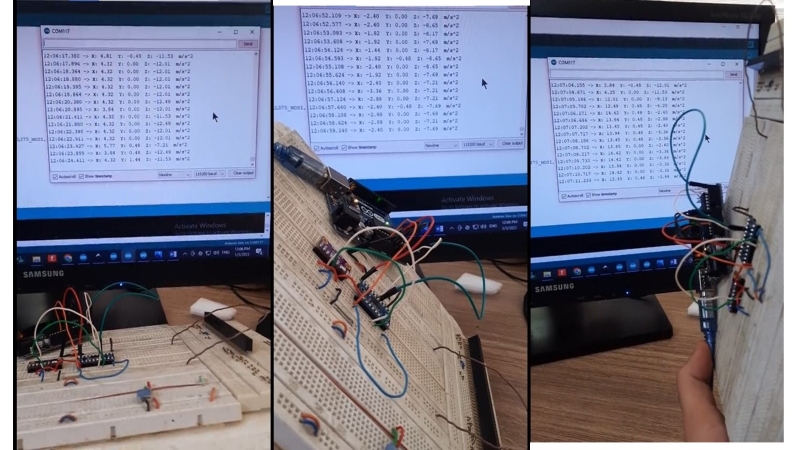
Step 4: Output
In Arduino IDE, open the Serial Monitor window from Tools>Serial Monitor.
If the connections are OK, three rows of X, Y, and Z outputs should be displayed together with their values. If you place the module on a fixed surface, after a few cycles, the numbers should be pretty much constant. Also, when the sensor is not moving, due to gravity, you should see an acceleration of 10g, and the number range for each axis should be 20 (for example, from -10 to +10). Now, hold the sensor at several fixed angles and see the outputs.