Contents

Interfacing ADXL345 Digital Accelerometer Module with Arduino

ADXL345 Accelerometer Module Features

ADXL345 accelerometer sensor can measure angle orientation and object path. The sensor can do that in three X, Y and Z axes. It can also measure dynamic and static acceleration forces. Dynamic acceleration force is due to motion and vibration and static acceleration is caused by gravity. The sensitivity range of the ADXL345 accelerometer sensor is from +-2g to +-16g. (g is approximately 9.8) For example, when this sensor is placed on a flat surface, its value is +1g in the direction of the z axis and zero in the direction of the x and z axes.

This sensor uses both I2C and SPI communicaton protocols. It can be used in robotics and flying robots, navigation devices, game consoles, 3D remote controllers, etc.

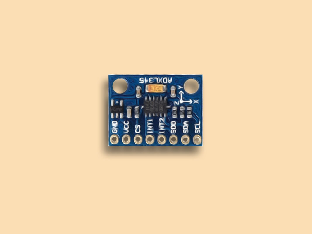
You can download the datasheet of this module here.  

ADXL345 Accelerometer Module Pinout

This sensor has 8 pins:

  • VCC: Module power supply – 3 to 6 V
  • GND: Ground
  • Cs: Chip Select
  • INT1: Interrupt 1 Out
  • INT2: Interrupt 2 Out
  • SDO: Serial Data Out
  • SDA: Serial Data
  • SCL: Serial Clock

You can see the pinout of this module in the image below. In this tutorial the two I2C pins have been used.

Required Materials

Hardware Components

Arduino UNO R3 × 1
ADXL345 Accelerometer Module × 1
Male to Male jumper wire × 1

Software Apps

Arduino IDE

Interfacing ADXL345 Accelerometer Module with Arduino

Step 1: Circuit

The following circuit shows how you should connect Arduino to ADXL345 sensor. Connect wires accordingly.

Step 2: Code

Upload the following code to Arduino.

/*
  ADXL345-Acceleration-Modole
  modified on 26 oct 2020
  by Amir Mohammad Shojaee @ Electropeak
  
Home
Based on howtomechatronics.com Example */ #include <Wire.h> // Wire library - used for I2C communication int ADXL345 = 0x53; // The ADXL345 sensor I2C address float X_out, Y_out, Z_out; // Outputs void setup() { Serial.begin(9600); Wire.begin(); // Initiate the Wire library Wire.beginTransmission(ADXL345); // Start communicating with the device Wire.write(0x2D); // Access/ talk to POWER_CTL Register - 0x2D Wire.write(8); // (8dec -> 0000 1000 binary) Bit D3 High for measuring enable Wire.endTransmission(); delay(10); } void loop() { // === Read acceleromter data === // Wire.beginTransmission(ADXL345); Wire.write(0x32); // Start with register 0x32 (ACCEL_XOUT_H) Wire.endTransmission(false); Wire.requestFrom(ADXL345, 6, true); // Read 6 registers total, each axis value is stored in 2 registers X_out = ( Wire.read()| Wire.read() << 8); // X-axis value X_out = X_out/256; //For a range of +-2g, we need to divide the raw values by 256, according to the datasheet Y_out = ( Wire.read()| Wire.read() << 8); // Y-axis value Y_out = Y_out/256; Z_out = ( Wire.read()| Wire.read() << 8); // Z-axis value Z_out = Z_out/256; Serial.print("Xa= "); Serial.print(X_out); delay(500); Serial.print(" Ya= "); Serial.print(Y_out); delay(500); Serial.print(" Za= "); Serial.println(Z_out); delay(500); }

The library needed for I2C connection is called at the beginning of the code. In the next step, the I2C address is written. This address is listed in the datasheet. Next, we put it in the measurement position. This is done by addressing the registry and the desired bit. Each axis contains 2 registers. The operation of reading the registers starts from the x-axis and this process must be repeated 6 times. Then, according to the +-2g sensitivity mentioned in the datasheet, we divide it by 256. Finally, the output value of each axis is displayed in Serial Monitor.
By moving the sensor in different directions, the following output in Serial Monitor changes as shown below.

Liked What You See?​
Get Updates And Learn From The Best​

Comments (2)

  • Tennis Kumar Reddy Reply

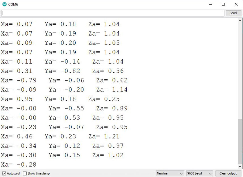
    i’m having issues when i try to read data from two adxl345 sensors using esp32 wroom 32d module, also I’ve connected the sdo pin od one of the adxl345 to vcc to change the default i2c address to avoid i2c address conflict, what I’m trying to achieve is to detect tilt angle using tow adxl345 sensors, the formula I’m using is :
    float tiltAngle1 = atan2(y1, z1) * 180.0 / PI;
    float tiltAngle2 = atan2(y2, z2) * 180.0 / PI;

    please help me with this

    December 8, 2023 at 7:11 am
    • Mohammad Damirchi Reply

      Hi Tennis,
      There is no need to use a sensor to measure rotation in one direction.
      With each of these sensors, you can calculate the rotation along the X and Y axes. ( If you want yaw rotation angle, you must use magnetometers.)
      You can use the tutorial in this link.
      Also, there are modules like this one that can measure and record angles without any additional work.
      If you want to decrease noise of accelerometer, you need to use gyroscope and sensor fusion algorithm like kalman filter.
      For this, you can use this library for arduino.

      December 13, 2023 at 7:24 am

Leave a Reply

Your email address will not be published. Required fields are marked *