Learn how to interface a 4×3 membrane matrix keypad with Arduino using this comprehensive tutorial. By following the steps outlined below, you can easily connect the keypad to your Arduino and start using its 12 buttons with only 7 pins on the microcontroller.
Features of the 4x3 Matrix Keypad
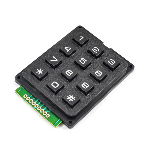
Keypads are one of the most popular components that are widely used in electronics. Everybody can communicate with the system by switches. Normally, every key occupies one digital pin of the microcontroller. But by using a 3×4 keypad you can reduce the occupied pins. With this module, you can use all 12 switches by occupying only 7 pins of the microcontroller.
How it works
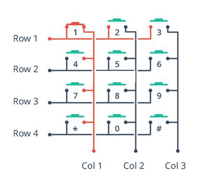
The Keypad 4×3 features a total of 12 buttons in Matrix form. Consider 4 rows as input and 3 columns as output. Each switch is connected from one side to a row and from the other side to a column. For example, if we press switch number 1, the input of this row is saved at the output of its column. The image below shows the internal circuit of this keyboard.
4x3 Matrix Keypad Pinout
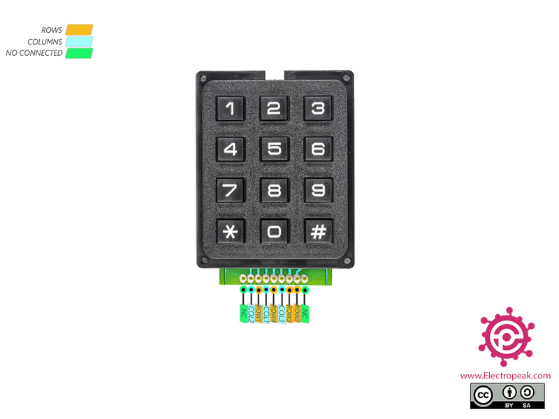
This module has 9 pins:
- ROW1: Input pin – Row 1
- ROW2: Input pin – Row 2
- ROW3: Input pin – Row 3
- ROW4: Input pin – Row 4
- COL1: Output pin – Column 1
- COL2: Output pin – Column 2
- COL3: Output pin – Column 3
- NC: Not used
You can see the pinout of this module here.
Required Materials
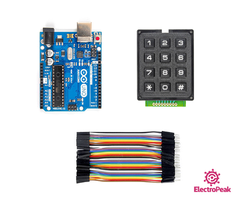
Hardware Components
Software Apps
Interfacing 4x3 Matrix Keypad with Arduino
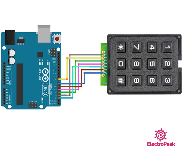
Step 1: Circuit
The following circuit shows how you should connect Arduino to this module. Connect wires accordingly.
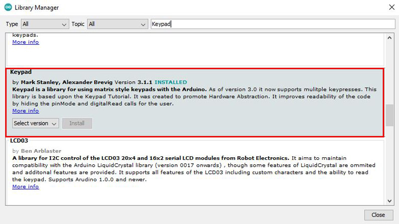
Step 2: Installing Library
Search for Keypad in the Arduino Library section and install it, as shown.
Note
If you need more help with installing a library on Arduino, read this tutorial: How to Install an Arduino Library
Step 3: Code
Upload the following code to Arduino.
   /*
  4x3-Membrance-Matrix-Keypad
  modified on 15 Nov 2020
  by Amir Mohammad Shojaee @ Electropeak
  Home

  based on Keypad Arduino Library Examples
*/

#include <Keypad.h>

const byte ROWS = 4; // Define the number of rows on the keypad
const byte COLS = 3; // Define the number of columns on the keypad
char keys[ROWS][COLS] = { // Matrix defining character to return for each key
  {'1','2','3'},
  {'4','5','6'},
  {'7','8','9'},
  {'*','0','#'}
};
byte rowPins[ROWS] = {8, 7, 6, 5}; //connect to the row pins (R0-R3) of the keypad
byte colPins[COLS] = {4, 3, 2}; //connect to the column pins (C0-C2) of the keypad
//initialize an instance of class
Keypad keypad = Keypad( makeKeymap(keys), rowPins, colPins, ROWS, COLS );

void setup(){
  Serial.begin(9600);
}

void loop(){
  char key = keypad.getKey();

  if (key){     // If key is pressed, send it to the Serial Monitor Window
    Serial.println(key);
  }
}
First, the Keypad library is included. Then you have to enter the number of columns and rows of keypads. A two-dimensional array of columns and rows is defined to display the character of each switch. Note that only characters are displayed in this code. In the next step 5 parameters are defined in the Keypad command. Then the “getkey()” command checks to see which switches are pressed. Finally, the compressed switch character appears in the Serial Monitor.
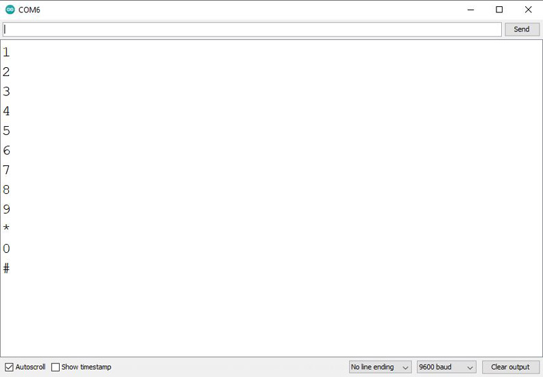
The output is as follows. As you can see, switches (first to the end) are pressed one after another and a special character for each is displayed on the Serial Monitor.