Contents

Interfacing 315/433 MHz RF Transmitter-Receiver Module with Arduino

Wirelessly connecting electronic devices is often necessary, and Radio Frequency (RF) equipment serves this purpose. RF modules enable communication using radio waves of varying frequencies and amplitudes, allowing information to be transmitted to the receiver over different distances.

315/433 MHz RF Transmitter-Receiver Module Features

The 315/433 MHz RF transmitter-receiver module is designed to operate at 433MHz and 315MHz frequencies. It consists of a transmitter and a receiver, making it ideal for wireless communication projects.

This module is produced in two different types: 315MHz and 433MHz.

Note

All modules that use the 315/433MHz frequency band can communicate with each other and there is no information security in this type of communication. If you need security, you must use encryption (locking) on the receiver and transmitter.

Note

This module has a one-way communication and can only send information to the receiver. If you want to communicate in both directions, you should use two pairs of this module.

Download the datasheet of this module here.

315/433 MHz RF Transmitter-Receiver Module Pinout

This module has 3 pins:

  • VIN: Module power supply
  • GND: Ground
  • Data: Data line for sending or transmitting the data

Required Materials

Arduino UNO R3 × 1
433MHz RF TRANSMITTER AND RECEIVER × 1
315MHz RF TRANSMITTER AND RECEIVER × 1
male-female jumper wire × 1

Hardware Components

Software Apps

Arduino IDE

Interfacing 315/433 MHz RF Transmitter-Receiver Module with Arduino

Step 1: Circuit

The following circuit shows how you should connect the Arduino Board to this module. Connect wires accordingly.

Step 2: Library

Install the following library on your Arduino.

https://github.com/sui77/rc-switch

Tip

If you need more help with installing a library on Arduino, read this tutorial: How to Install an Arduino Library

Step 3: Code

Upload the following code to the Arduino Board connected to the transmitter side.

/*
  Example for different sending methods
  
  https://github.com/sui77/rc-switch/
  
*/

#include <RCSwitch.h>

RCSwitch mySwitch = RCSwitch();

void setup() {

  Serial.begin(9600);
  
  // Transmitter is connected to Arduino Pin #10  
  mySwitch.enableTransmit(10);
  
  // Optional set protocol (default is 1, will work for most outlets)
  // mySwitch.setProtocol(2);

  // Optional set pulse length.
  // mySwitch.setPulseLength(320);
  
  // Optional set number of transmission repetitions.
  // mySwitch.setRepeatTransmit(15);
  
}

void loop() {

  /* See Example: TypeA_WithDIPSwitches */
  mySwitch.switchOn("11111", "00010");
  delay(1000);
  mySwitch.switchOff("11111", "00010");
  delay(1000);

  /* Same switch as above, but using decimal code */
  mySwitch.send(5393, 24);
  delay(1000);  
  mySwitch.send(5396, 24);
  delay(1000);  

  /* Same switch as above, but using binary code */
  mySwitch.send("000000000001010100010001");
  delay(1000);  
  mySwitch.send("000000000001010100010100");
  delay(1000);

  /* Same switch as above, but tri-state code */ 
  mySwitch.sendTriState("00000FFF0F0F");
  delay(1000);  
  mySwitch.sendTriState("00000FFF0FF0");
  delay(1000);

  delay(20000);
} 

Upload the following code to the Arduino Board connected to the receiver side

/*
  Simple example for receiving
  
  https://github.com/sui77/rc-switch/
*/

#include <RCSwitch.h>

RCSwitch mySwitch = RCSwitch();

void setup() {
  Serial.begin(9600);
  mySwitch.enableReceive(0);  // Receiver on interrupt 0 => that is pin #2
}

void loop() {
  if (mySwitch.available()) {
    
    int value = mySwitch.getReceivedValue();
    
    if (value == 0) {
      Serial.print("Unknown encoding");
    } else {
      Serial.print("Received ");
      Serial.print( mySwitch.getReceivedValue() );
      Serial.print(" / ");
      Serial.print( mySwitch.getReceivedBitlength() );
      Serial.print("bit ");
      Serial.print("Protocol: ");
      Serial.println( mySwitch.getReceivedProtocol() );
    }

    mySwitch.resetAvailable();
  }
}

This code is to test the connection between the transmitter and receiver.

The receiver can see the sent data in the Serial monitor.

The 315/433 MHz RF transmitter-receiver module offers a convenient solution for wireless communication between electronic devices. By following the provided circuit diagram, library installation steps, and code upload instructions, you can easily interface this module with an Arduino board. Remember to ensure data security by implementing encryption if required for your project.

Liked What You See?​
Get Updates And Learn From The Best​

Comments (8)

  • Desmond Reply

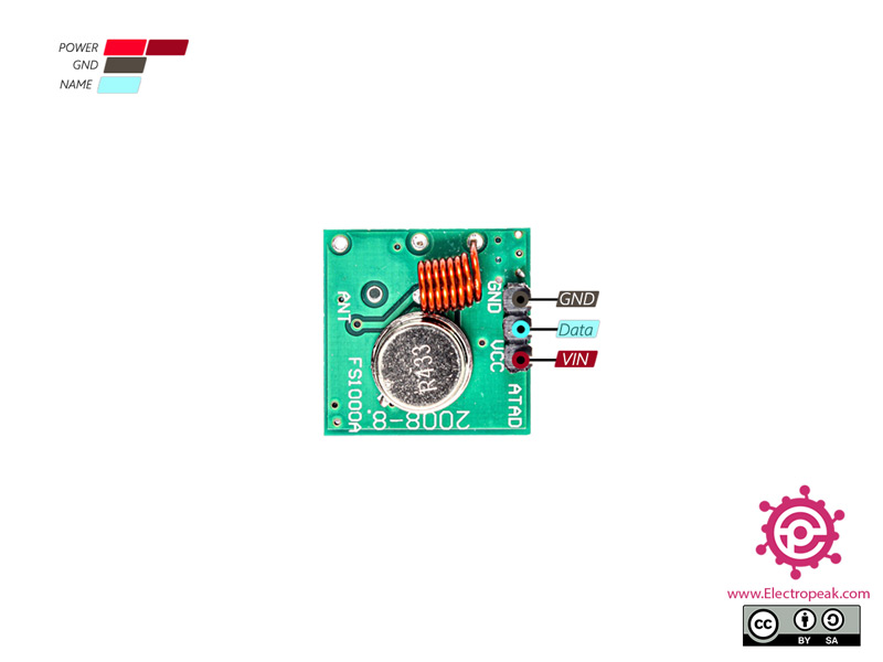
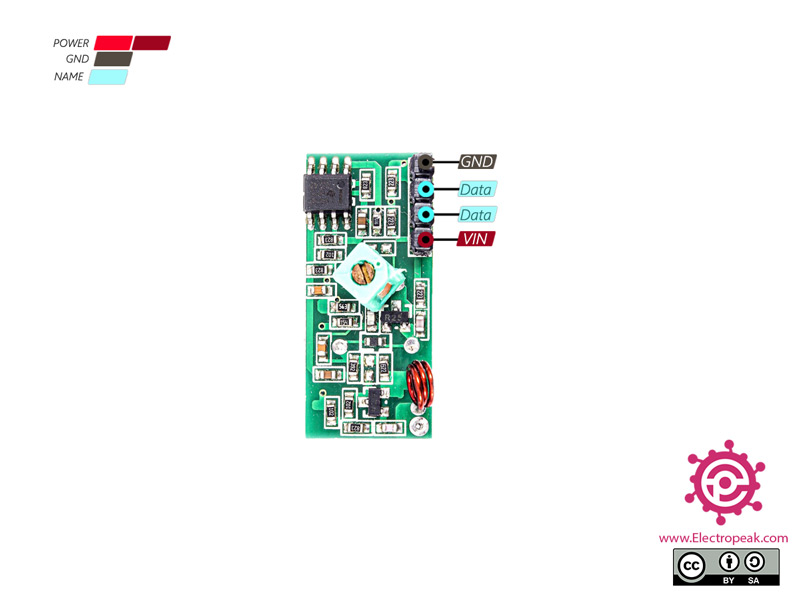
    Are the two data pins of the rx module connected together?

    August 1, 2022 at 11:45 am
    • Mehran Maleki Reply

      Hi,
      Yes, they’re connected to each other.

      August 1, 2022 at 4:35 pm
  • Subodh Reply

    Can I interface this with soil moisture sensor.

    September 21, 2022 at 11:35 am
    • Ali Abdolmaleki Reply

      Hi Dear
      you can get soil moisture sensor data with you a arduino board and send from RF Transmitter to others.

      March 30, 2023 at 9:25 am
  • Kur Boli Reply

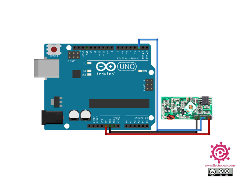
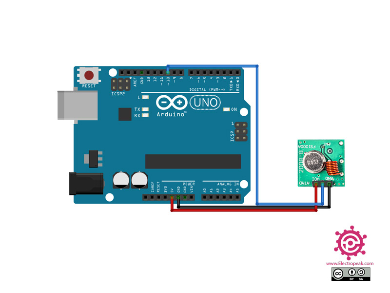
    Your connection diagram in the image is wrong , ,i was following the picture where it is connected to the arduino and fried my receiver
    Good job at paying attention to what you post 🙂 , change it !!!

    March 28, 2023 at 8:18 pm
    • Ali Abdolmaleki Reply

      Hi.
      you right my friend.
      i will change it Asap.

      March 30, 2023 at 9:30 am
  • pusi kur Reply

    Change the image of the connection , i fried my board thanks to you 🙂 Well done 🙂

    March 28, 2023 at 8:20 pm
    • Ali Abdolmaleki Reply

      Hi
      image of the Connections is correct.
      let me know how did you done?

      March 30, 2023 at 9:27 am

Leave a Reply

Your email address will not be published. Required fields are marked *