2.42 INCH OLED Display Module Features
OLED displays are high contrast and high-resolution displays, so they provide a good readability for users. There is no backlight on OLED, and it uses independent-illuminated pixels. So, it is thinner and more elegant in compare to LCDs.
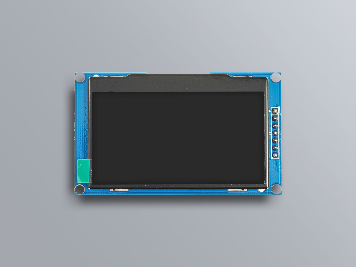
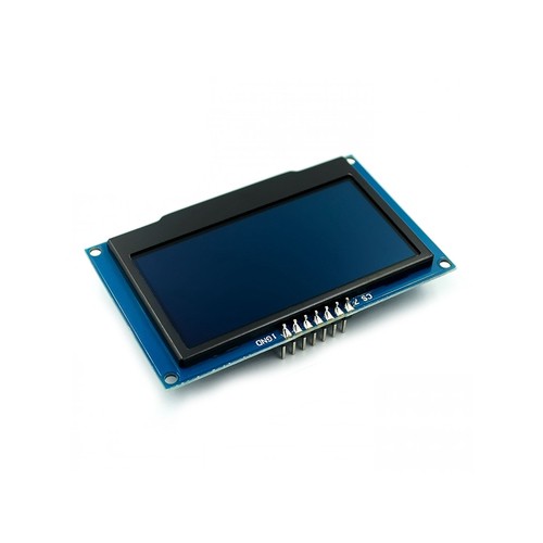
This 2.42 INCH OLED display is single color and the resolution is 128×64 pixels. The driver chip is SSD1309.
You can download the datasheet of this module here.
2.42 INCH OLED Display Module Pinout
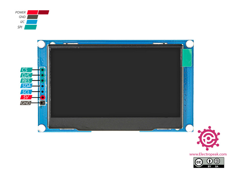
This module has 7 pins:
- VCC: Module power supply – 5 V
- GND: Ground
- SCL: I2C clock
- SDA: I2C data
- CS: Module Select
- D/C: Data/Command
- RES: Reset
You can see the pinout of this module in the image below.
Required Materials
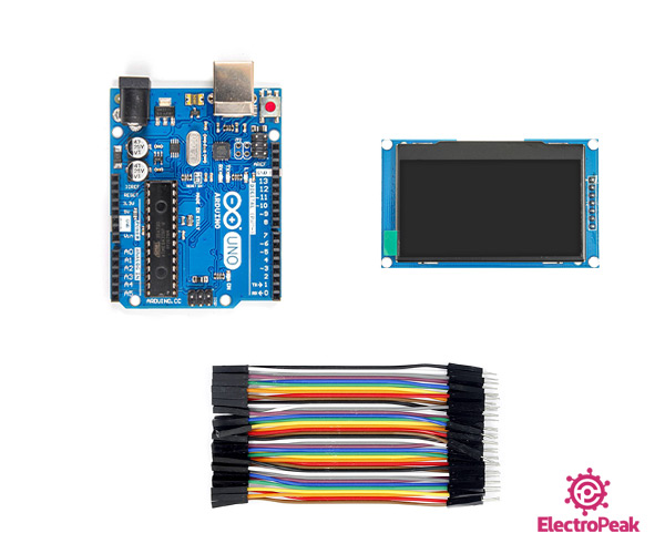
Hardware Components
Software Apps
Interfacing 2.42 INCH OLED Display Module with Arduino
Step 1: Circuit
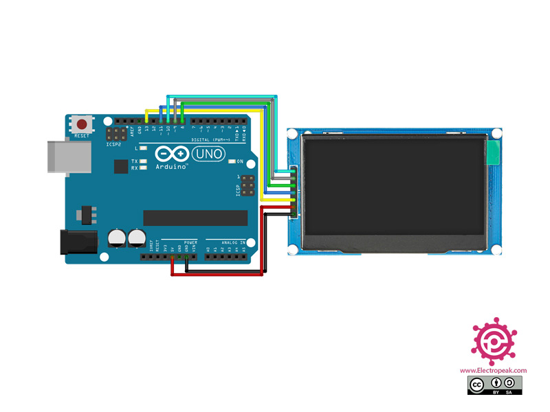
The following circuit shows how you should connect Arduino to this module. Connect wires accordingly.
Step 2: Library
Install the following Library on your Arduino.
Note
If you need more help with installing a library on Arduino, read this tutorial: How to Install an Arduino Library
Step 3: Code
Upload the following code to Arduino.
/*

  GraphicsTest.ino

  Universal 8bit Graphics Library (https://github.com/olikraus/u8g2/)

  Copyright (c) 2016, [email protected]
  All rights reserved.

  Redistribution and use in source and binary forms, with or without modification,
  are permitted provided that the following conditions are met:

  * Redistributions of source code must retain the above copyright notice, this list
    of conditions and the following disclaimer.

  * Redistributions in binary form must reproduce the above copyright notice, this
    list of conditions and the following disclaimer in the documentation and/or other
    materials provided with the distribution.

  THIS SOFTWARE IS PROVIDED BY THE COPYRIGHT HOLDERS AND
  CONTRIBUTORS "AS IS" AND ANY EXPRESS OR IMPLIED WARRANTIES,
  INCLUDING, BUT NOT LIMITED TO, THE IMPLIED WARRANTIES OF
  MERCHANTABILITY AND FITNESS FOR A PARTICULAR PURPOSE ARE
  DISCLAIMED. IN NO EVENT SHALL THE COPYRIGHT HOLDER OR
  CONTRIBUTORS BE LIABLE FOR ANY DIRECT, INDIRECT, INCIDENTAL,
  SPECIAL, EXEMPLARY, OR CONSEQUENTIAL DAMAGES (INCLUDING, BUT
  NOT LIMITED TO, PROCUREMENT OF SUBSTITUTE GOODS OR SERVICES;
  LOSS OF USE, DATA, OR PROFITS; OR BUSINESS INTERRUPTION) HOWEVER
  CAUSED AND ON ANY THEORY OF LIABILITY, WHETHER IN CONTRACT,
  STRICT LIABILITY, OR TORT (INCLUDING NEGLIGENCE OR OTHERWISE)
  ARISING IN ANY WAY OUT OF THE USE OF THIS SOFTWARE, EVEN IF
  ADVISED OF THE POSSIBILITY OF SUCH DAMAGE.

*/

#include <Arduino.h>
#include <U8g2lib.h>

#ifdef U8X8_HAVE_HW_SPI
#include <SPI.h>
#endif
#ifdef U8X8_HAVE_HW_I2C
#include <Wire.h>
#endif

U8G2_SSD1309_128X64_NONAME0_F_4W_HW_SPI u8g2(U8G2_R0, /* cs=*/ 10, /* dc=*/ 9, /* reset=*/ 8);

void u8g2_prepare(void) {
  u8g2.setFont(u8g2_font_6x10_tf);
  u8g2.setFontRefHeightExtendedText();
  u8g2.setDrawColor(1);
  u8g2.setFontPosTop();
  u8g2.setFontDirection(0);
}

void u8g2_box_frame(uint8_t a) {
  u8g2.drawStr( 0, 0, "drawBox");
  u8g2.drawBox(5,10,20,10);
  u8g2.drawBox(10+a,15,30,7);
  u8g2.drawStr( 0, 30, "drawFrame");
  u8g2.drawFrame(5,10+30,20,10);
  u8g2.drawFrame(10+a,15+30,30,7);
}

void u8g2_disc_circle(uint8_t a) {
  u8g2.drawStr( 0, 0, "drawDisc");
  u8g2.drawDisc(10,18,9);
  u8g2.drawDisc(24+a,16,7);
  u8g2.drawStr( 0, 30, "drawCircle");
  u8g2.drawCircle(10,18+30,9);
  u8g2.drawCircle(24+a,16+30,7);
}

void u8g2_r_frame(uint8_t a) {
  u8g2.drawStr( 0, 0, "drawRFrame/Box");
  u8g2.drawRFrame(5, 10,40,30, a+1);
  u8g2.drawRBox(50, 10,25,40, a+1);
}

void u8g2_string(uint8_t a) {
  u8g2.setFontDirection(0);
  u8g2.drawStr(30+a,31, " 0");
  u8g2.setFontDirection(1);
  u8g2.drawStr(30,31+a, " 90");
  u8g2.setFontDirection(2);
  u8g2.drawStr(30-a,31, " 180");
  u8g2.setFontDirection(3);
  u8g2.drawStr(30,31-a, " 270");
}

void u8g2_line(uint8_t a) {
  u8g2.drawStr( 0, 0, "drawLine");
  u8g2.drawLine(7+a, 10, 40, 55);
  u8g2.drawLine(7+a*2, 10, 60, 55);
  u8g2.drawLine(7+a*3, 10, 80, 55);
  u8g2.drawLine(7+a*4, 10, 100, 55);
}

void u8g2_triangle(uint8_t a) {
  uint16_t offset = a;
  u8g2.drawStr( 0, 0, "drawTriangle");
  u8g2.drawTriangle(14,7, 45,30, 10,40);
  u8g2.drawTriangle(14+offset,7-offset, 45+offset,30-offset, 57+offset,10-offset);
  u8g2.drawTriangle(57+offset*2,10, 45+offset*2,30, 86+offset*2,53);
  u8g2.drawTriangle(10+offset,40+offset, 45+offset,30+offset, 86+offset,53+offset);
}

void u8g2_ascii_1() {
  char s[2] = " " ;
  uint8_t x, y;
  u8g2.drawStr( 0, 0, "ASCII page 1");
  for( y = 0; y < 6; y++ ) {
    for( x = 0; x < 16; x++ ) {
      s[0] = y*16 + x + 32;
      u8g2.drawStr(x*7, y*10+10, s);
    }
  }
}

void u8g2_ascii_2() {
  char s[2] = " " ;
  uint8_t x, y;
  u8g2.drawStr( 0, 0, "ASCII page 2");
  for( y = 0; y < 6; y++ ) {
    for( x = 0; x < 16; x++ ) {
      s[0] = y*16 + x + 160;
      u8g2.drawStr(x*7, y*10+10, s);
    }
  }
}

void u8g2_extra_page(uint8_t a)
{
  u8g2.drawStr( 0, 0, "Unicode");
  u8g2.setFont(u8g2_font_unifont_t_symbols);
  u8g2.setFontPosTop();
  u8g2.drawUTF8(0, 24, "☀ ☁");
  switch(a) {
    case 0:
    case 1:
    case 2:
    case 3:
      u8g2.drawUTF8(a*3, 36, "☂");
      break;
    case 4:
    case 5:
    case 6:
    case 7:
      u8g2.drawUTF8(a*3, 36, "☔");
      break;
  }
}

#define cross_width 24
#define cross_height 24
static const unsigned char cross_bits[] U8X8_PROGMEM  = {
  0x00, 0x18, 0x00, 0x00, 0x24, 0x00, 0x00, 0x24, 0x00, 0x00, 0x42, 0x00,
  0x00, 0x42, 0x00, 0x00, 0x42, 0x00, 0x00, 0x81, 0x00, 0x00, 0x81, 0x00,
  0xC0, 0x00, 0x03, 0x38, 0x3C, 0x1C, 0x06, 0x42, 0x60, 0x01, 0x42, 0x80,
  0x01, 0x42, 0x80, 0x06, 0x42, 0x60, 0x38, 0x3C, 0x1C, 0xC0, 0x00, 0x03,
  0x00, 0x81, 0x00, 0x00, 0x81, 0x00, 0x00, 0x42, 0x00, 0x00, 0x42, 0x00,
  0x00, 0x42, 0x00, 0x00, 0x24, 0x00, 0x00, 0x24, 0x00, 0x00, 0x18, 0x00, };

#define cross_fill_width 24
#define cross_fill_height 24
static const unsigned char cross_fill_bits[] U8X8_PROGMEM  = {
  0x00, 0x00, 0x00, 0x00, 0x00, 0x00, 0x18, 0x00, 0x18, 0x64, 0x00, 0x26,
  0x84, 0x00, 0x21, 0x08, 0x81, 0x10, 0x08, 0x42, 0x10, 0x10, 0x3C, 0x08,
  0x20, 0x00, 0x04, 0x40, 0x00, 0x02, 0x80, 0x00, 0x01, 0x80, 0x18, 0x01,
  0x80, 0x18, 0x01, 0x80, 0x00, 0x01, 0x40, 0x00, 0x02, 0x20, 0x00, 0x04,
  0x10, 0x3C, 0x08, 0x08, 0x42, 0x10, 0x08, 0x81, 0x10, 0x84, 0x00, 0x21,
  0x64, 0x00, 0x26, 0x18, 0x00, 0x18, 0x00, 0x00, 0x00, 0x00, 0x00, 0x00, };

#define cross_block_width 14
#define cross_block_height 14
static const unsigned char cross_block_bits[] U8X8_PROGMEM  = {
  0xFF, 0x3F, 0x01, 0x20, 0x01, 0x20, 0x01, 0x20, 0x01, 0x20, 0x01, 0x20,
  0xC1, 0x20, 0xC1, 0x20, 0x01, 0x20, 0x01, 0x20, 0x01, 0x20, 0x01, 0x20,
  0x01, 0x20, 0xFF, 0x3F, };

void u8g2_bitmap_overlay(uint8_t a) {
  uint8_t frame_size = 28;

  u8g2.drawStr(0, 0, "Bitmap overlay");

  u8g2.drawStr(0, frame_size + 12, "Solid / transparent");
  u8g2.setBitmapMode(false /* solid */);
  u8g2.drawFrame(0, 10, frame_size, frame_size);
  u8g2.drawXBMP(2, 12, cross_width, cross_height, cross_bits);
  if(a & 4)
    u8g2.drawXBMP(7, 17, cross_block_width, cross_block_height, cross_block_bits);

  u8g2.setBitmapMode(true /* transparent*/);
  u8g2.drawFrame(frame_size + 5, 10, frame_size, frame_size);
  u8g2.drawXBMP(frame_size + 7, 12, cross_width, cross_height, cross_bits);
  if(a & 4)
    u8g2.drawXBMP(frame_size + 12, 17, cross_block_width, cross_block_height, cross_block_bits);
}

void u8g2_bitmap_modes(uint8_t transparent) {
  const uint8_t frame_size = 24;

  u8g2.drawBox(0, frame_size * 0.5, frame_size * 5, frame_size);
  u8g2.drawStr(frame_size * 0.5, 50, "Black");
  u8g2.drawStr(frame_size * 2, 50, "White");
  u8g2.drawStr(frame_size * 3.5, 50, "XOR");

  if(!transparent) {
    u8g2.setBitmapMode(false /* solid */);
    u8g2.drawStr(0, 0, "Solid bitmap");
  } else {
    u8g2.setBitmapMode(true /* transparent*/);
    u8g2.drawStr(0, 0, "Transparent bitmap");
  }
  u8g2.setDrawColor(0);// Black
  u8g2.drawXBMP(frame_size * 0.5, 24, cross_width, cross_height, cross_bits);
  u8g2.setDrawColor(1); // White
  u8g2.drawXBMP(frame_size * 2, 24, cross_width, cross_height, cross_bits);
  u8g2.setDrawColor(2); // XOR
  u8g2.drawXBMP(frame_size * 3.5, 24, cross_width, cross_height, cross_bits);
}

uint8_t draw_state = 0;

void draw(void) {
  u8g2_prepare();
  switch(draw_state >> 3) {
    case 0: u8g2_box_frame(draw_state&7); break;
    case 1: u8g2_disc_circle(draw_state&7); break;
    case 2: u8g2_r_frame(draw_state&7); break;
    case 3: u8g2_string(draw_state&7); break;
    case 4: u8g2_line(draw_state&7); break;
    case 5: u8g2_triangle(draw_state&7); break;
    case 6: u8g2_ascii_1(); break;
    case 7: u8g2_ascii_2(); break;
    case 8: u8g2_extra_page(draw_state&7); break;
    case 9: u8g2_bitmap_modes(0); break;
    case 10: u8g2_bitmap_modes(1); break;
    case 11: u8g2_bitmap_overlay(draw_state&7); break;
  }
}


void setup(void) {
  u8g2.begin();
}

void loop(void) {
  // picture loop
  u8g2.clearBuffer();
  draw();
  u8g2.sendBuffer();

  // increase the state
  draw_state++;
  if ( draw_state >= 12*8 )
    draw_state = 0;

  // deley between each page
  delay(100);

}
This code is for testing the display and shows various graphical shapes and designs.

Comments (19)
there is always this error:
Arduino:1.8.15 (Windows 10), Scheda:”Arduino Uno”
sketch_jan08c:1:12: fatal error: HyperDisplay_UG2856KLBAG01_I2C.h: No such file or directory
#include “HyperDisplay_UG2856KLBAG01_I2C.h”
^~~~~~~~~~~~~~~~~~~~~~~~~~~~~~~~~~
compilation terminated.
exit status 1
HyperDisplay_UG2856KLBAG01_I2C.h: No such file or directory
Hi.
It seems that the library used in this article has been out of date. The code will be updated soon.
The library and the code are both updated. You can try them now.
how do I connect this display to the arduino mega?
I am having a lot of difficulty, it seems that there are some differences between mega and uno.
Well, according to my knowledge, there should be no significant difference between them. The display is easily connected to the Arduino Mega board just like Uno. Just remember, the SPI pins on Arduino Mega are not the same with Uno. D50, D51 and D52 are the MISO, MOSI and SCK pins in the Arduino Mega board. So that’s one difference in wiring. And just for the programming, you need to choose the right board and PORT in the Arduino IDE tools settings.
– but how to connect Arduino with OLED 2.42″ but with I2C ?
How can I connect OLED to atmega328 without Arduino and using a program written in C language (using Atmel studio)?
Where to get the 1309 library for AVR
Hello I want to use this display with ESP32 any suggestions
Hi.
you can use the same library
https://github.com/olikraus/u8g2/
just you need to connect SPI/I2C ESP32 Pinout.
hello, how can I connect a 2.42″ I2C oled?
Hi Yusuf,
If you want to connect this display using the I2C interface, you should change the jumper on the back of the board. The information on the board will guide you (in this case, change R4 to R3 and also add a resistor to R5).
In the code section, use one of the examples from that library and test each setting for this specific mode. Before doing that, use an I2C Scanner to check if there is an address and what the address is. If there is no address, you need to check the wiring.
Excause me, I want to use this display with ATmega32u4(LEONARDO), any circuit or code need to be changed?
Hi Rick,
As far as I know, there’s no need to change anything.
its not working for me i connected everything my board is this “ACEIRMIC 2.42 inch oled 1309:” i havent done any microsoldering yet i just tried this tutorial straight from the box im using arduino uno
Hi lio,
Start by checking the mode of your OLED display (Whether it’s SPI or I2C, you can find that information on the back of the board).
Then, try using examples provided by the library to test all modes of the SSD1309. You might have better luck with a different mode.
Your Uno example worked well but I need the memory of a Mega. What would the SSD1309 init look like for a Mega?
U8G2_SSD1309_128X64_NONAME0_F_4W_HW_SPI u8g2(U8G2_R0, /* cs=*/ 10, /* dc=*/ 9, /* reset=*/ 8); works ok for the uno…
https://www.amazon.com/dp/B0C4PQF4RM?psc=1&ref=ppx_yo2ov_dt_b_product_details for the oled I used.
Hi,
You don’t need to make any changes, just ensure you connect to the correct SPI pins on the Arduino Mega.
In the Arduino UNO, the SPI pins are 11, 12, and 13, but on the Arduino Mega, they are 50, 51, and 52 (refer to the pinout of the Arduino Mega).
Additionally, consider changing pins 8, 9, and 10 in the configuration line to ones closer to the SPI pins of the Mega for easier wiring (it’s better to set the CS pin to 53).
What would happen if I used 7.4v instead of 3-5? I’ve added this sceen to my project recently and my esp32 has a little too much stress powering it from its own voltage regulator it seems but my raw voltage is 7.4v from 4 series/parallel batteries.
Hello Antoine,
Using a 7.4V power source directly on your OLED module could damage it. I suggest using a linear regulator like the AMS1117-5V to step down the 7.4V to 5V.
OLEDs typically have low power consumption, so this setup should work well.