
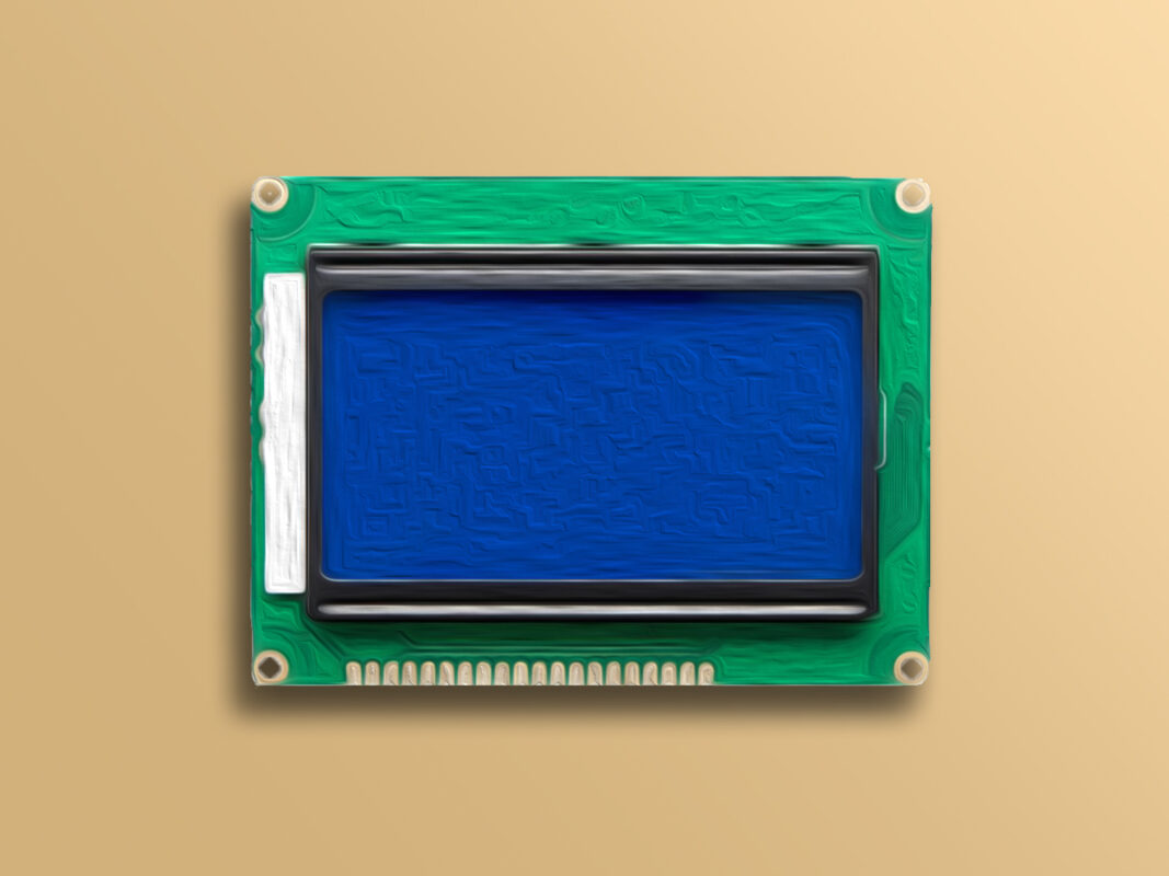
128x64 Graphical LCD Display Features
Ordinary LCDs can only display simple text or numbers within a fixed size. But in 128×64 graphical LCD display, there is 128×64 = 8192 dots, which is equivalent to 8192 pixels. So, it can display not only simple text or numbers within a fixed size but also simple graphics.
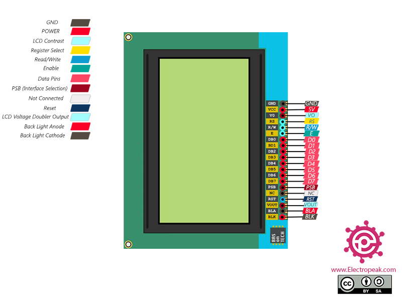
128x64 Graphical LCD Display Pinout
This module has 20 pins:
- GND: Ground
- VCC: Module power supply – 5 V
- VO: LCD Contrast
- RS: Register Select Pin
- R/W: Write/ Read selection
- E: Enable Signal
- D0-7: Data Bus
- PSB: Interface selection (0 for serial communication, 1 for 8-bit parallel communication)
- NC: Not Connected
- RST: Reset
- Vout: LCD Voltage Output (Vout < 7V)
- BLA: Power Supply for Backlight+
- BLK: Power Supply for Backlight-
You can see the pinout of this module in the image below.
Required Material
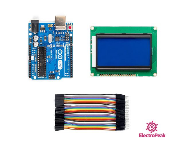
Hardware component
Software Apps
Interfacing 128x64 Graphical LCD Display with Arduino
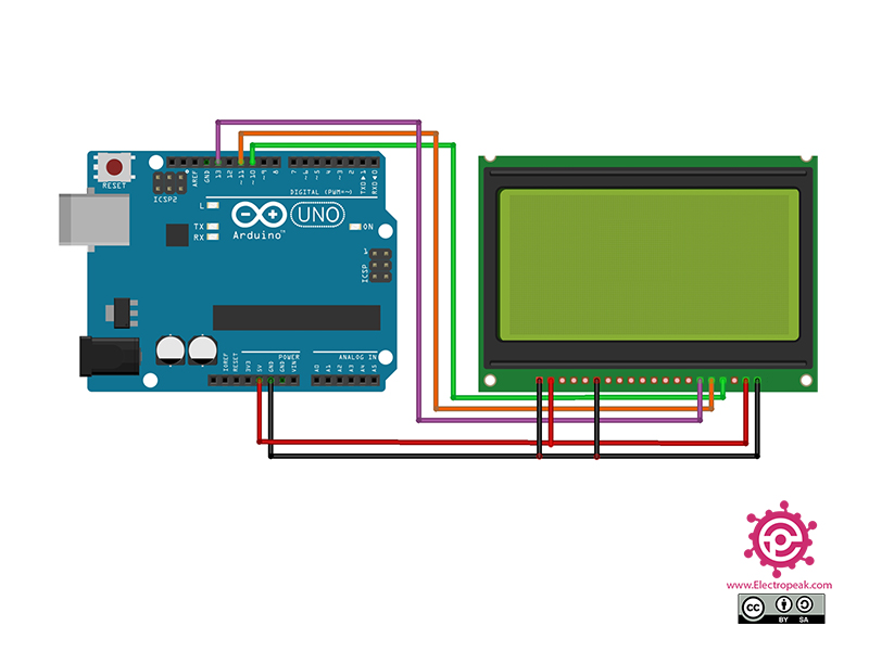
Step 1: Circuit
The following circuit shows how you should connect Arduino to the Display. Connect wires accordingly.
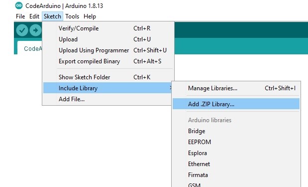
Step 2: Library
Download the u8glib library here. Then go to the Include Library and install it.
Tip
If you need more help with installing a library on Arduino, read this tutorial: How to Install an Arduino Library
Step 3: Code
Upload the following code to your Arduino. After that, open Serial Monitor.
    /*
Modified on Dec 2, 2020
Modified by MehranMaleki from Arduino Examples
Home
*/


/*

  GraphicsTest.pde

  >>> Before compiling: Please remove comment from the constructor of the
  >>> connected graphics display (see below).

  Universal 8bit Graphics Library, https://github.com/olikraus/u8glib/

  Copyright (c) 2012, [email protected]
  All rights reserved.

  Redistribution and use in source and binary forms, with or without modification,
  are permitted provided that the following conditions are met:

  * Redistributions of source code must retain the above copyright notice, this list
    of conditions and the following disclaimer.

  * Redistributions in binary form must reproduce the above copyright notice, this
    list of conditions and the following disclaimer in the documentation and/or other
    materials provided with the distribution.

  THIS SOFTWARE IS PROVIDED BY THE COPYRIGHT HOLDERS AND
  CONTRIBUTORS "AS IS" AND ANY EXPRESS OR IMPLIED WARRANTIES,
  INCLUDING, BUT NOT LIMITED TO, THE IMPLIED WARRANTIES OF
  MERCHANTABILITY AND FITNESS FOR A PARTICULAR PURPOSE ARE
  DISCLAIMED. IN NO EVENT SHALL THE COPYRIGHT HOLDER OR
  CONTRIBUTORS BE LIABLE FOR ANY DIRECT, INDIRECT, INCIDENTAL,
  SPECIAL, EXEMPLARY, OR CONSEQUENTIAL DAMAGES (INCLUDING, BUT
  NOT LIMITED TO, PROCUREMENT OF SUBSTITUTE GOODS OR SERVICES;
  LOSS OF USE, DATA, OR PROFITS; OR BUSINESS INTERRUPTION) HOWEVER
  CAUSED AND ON ANY THEORY OF LIABILITY, WHETHER IN CONTRACT,
  STRICT LIABILITY, OR TORT (INCLUDING NEGLIGENCE OR OTHERWISE)
  ARISING IN ANY WAY OUT OF THE USE OF THIS SOFTWARE, EVEN IF
  ADVISED OF THE POSSIBILITY OF SUCH DAMAGE.


*/


#include "U8glib.h"

// setup u8g object, please remove comment from one of the following constructor calls
// IMPORTANT NOTE: The following list is incomplete. The complete list of supported
// devices with all constructor calls is here: https://github.com/olikraus/u8glib/wiki/device
//U8GLIB_NHD27OLED_BW u8g(13, 11, 10, 9);	// SPI Com: SCK = 13, MOSI = 11, CS = 10, A0 = 9
//U8GLIB_NHD27OLED_2X_BW u8g(13, 11, 10, 9);	// SPI Com: SCK = 13, MOSI = 11, CS = 10, A0 = 9
//U8GLIB_NHD27OLED_GR u8g(13, 11, 10, 9);	// SPI Com: SCK = 13, MOSI = 11, CS = 10, A0 = 9
//U8GLIB_NHD27OLED_2X_GR u8g(13, 11, 10, 9);	// SPI Com: SCK = 13, MOSI = 11, CS = 10, A0 = 9
//U8GLIB_NHD31OLED_BW u8g(13, 11, 10, 9);	// SPI Com: SCK = 13, MOSI = 11, CS = 10, A0 = 9
//U8GLIB_NHD31OLED_2X_BW u8g(13, 11, 10, 9);	// SPI Com: SCK = 13, MOSI = 11, CS = 10, A0 = 9
//U8GLIB_NHD31OLED_GR u8g(13, 11, 10, 9);	// SPI Com: SCK = 13, MOSI = 11, CS = 10, A0 = 9
//U8GLIB_NHD31OLED_2X_GR u8g(13, 11, 10, 9);	// SPI Com: SCK = 13, MOSI = 11, CS = 10, A0 = 9
//U8GLIB_DOGS102 u8g(13, 11, 10, 9, 8);		// SPI Com: SCK = 13, MOSI = 11, CS = 10, A0 = 9
//U8GLIB_DOGM132 u8g(13, 11, 10, 9);		// SPI Com: SCK = 13, MOSI = 11, CS = 10, A0 = 9
//U8GLIB_DOGM128 u8g(13, 11, 10, 9);		// SPI Com: SCK = 13, MOSI = 11, CS = 10, A0 = 9
//U8GLIB_DOGM128_2X u8g(13, 11, 10, 9);		// SPI Com: SCK = 13, MOSI = 11, CS = 10, A0 = 9
U8GLIB_ST7920_128X64_4X u8g(10);
//U8GLIB_ST7920_128X64_1X u8g(8, 9, 10, 11, 4, 5, 6, 7, 18, 17, 16);   // 8Bit Com: D0..D7: 8,9,10,11,4,5,6,7 en=18, di=17,rw=16
//U8GLIB_ST7920_128X64_4X u8g(8, 9, 10, 11, 4, 5, 6, 7, 18, 17, 16);   // 8Bit Com: D0..D7: 8,9,10,11,4,5,6,7 en=18, di=17,rw=16
//U8GLIB_ST7920_128X64_1X u8g(18, 16, 17);	// SPI Com: SCK = en = 18, MOSI = rw = 16, CS = di = 17
//U8GLIB_ST7920_128X64_4X u8g(18, 16, 17);	// SPI Com: SCK = en = 18, MOSI = rw = 16, CS = di = 17
//U8GLIB_ST7920_192X32_1X u8g(8, 9, 10, 11, 4, 5, 6, 7, 18, 17, 16);   // 8Bit Com: D0..D7: 8,9,10,11,4,5,6,7 en=18, di=17,rw=16
//U8GLIB_ST7920_192X32_4X u8g(8, 9, 10, 11, 4, 5, 6, 7, 18, 17, 16);   // 8Bit Com: D0..D7: 8,9,10,11,4,5,6,7 en=18, di=17,rw=16
//U8GLIB_ST7920_192X32_1X u8g(18, 16, 17);	// SPI Com: SCK = en = 18, MOSI = rw = 16, CS = di = 17
//U8GLIB_ST7920_192X32_4X u8g(18, 16, 17);	// SPI Com: SCK = en = 18, MOSI = rw = 16, CS = di = 17
//U8GLIB_ST7920_192X32_1X u8g(13, 11, 10);	// SPI Com: SCK = en = 13, MOSI = rw = 11, CS = di = 10
//U8GLIB_ST7920_192X32_4X u8g(10);		// SPI Com: SCK = en = 13, MOSI = rw = 11, CS = di = 10, HW SPI
//U8GLIB_ST7920_202X32_1X u8g(8, 9, 10, 11, 4, 5, 6, 7, 18, 17, 16);   // 8Bit Com: D0..D7: 8,9,10,11,4,5,6,7 en=18, di=17,rw=16
//U8GLIB_ST7920_202X32_4X u8g(8, 9, 10, 11, 4, 5, 6, 7, 18, 17, 16);   // 8Bit Com: D0..D7: 8,9,10,11,4,5,6,7 en=18, di=17,rw=16
//U8GLIB_ST7920_202X32_1X u8g(18, 16, 17);	// SPI Com: SCK = en = 18, MOSI = rw = 16, CS = di = 17
//U8GLIB_ST7920_202X32_4X u8g(18, 16, 17);	// SPI Com: SCK = en = 18, MOSI = rw = 16, CS = di = 17
//U8GLIB_LM6059 u8g(13, 11, 10, 9);		// SPI Com: SCK = 13, MOSI = 11, CS = 10, A0 = 9
//U8GLIB_LM6063 u8g(13, 11, 10, 9);		// SPI Com: SCK = 13, MOSI = 11, CS = 10, A0 = 9
//U8GLIB_DOGXL160_BW u8g(10, 9);		// SPI Com: SCK = 13, MOSI = 11, CS = 10, A0 = 9
//U8GLIB_DOGXL160_GR u8g(13, 11, 10, 9);	// SPI Com: SCK = 13, MOSI = 11, CS = 10, A0 = 9
//U8GLIB_DOGXL160_2X_BW u8g(13, 11, 10, 9);	// SPI Com: SCK = 13, MOSI = 11, CS = 10, A0 = 9
//U8GLIB_DOGXL160_2X_GR u8g(13, 11, 10, 9);	// SPI Com: SCK = 13, MOSI = 11, CS = 10, A0 = 9
//U8GLIB_PCD8544 u8g(13, 11, 10, 9, 8);		// SPI Com: SCK = 13, MOSI = 11, CS = 10, A0 = 9, Reset = 8
//U8GLIB_PCF8812 u8g(13, 11, 10, 9, 8);		// SPI Com: SCK = 13, MOSI = 11, CS = 10, A0 = 9, Reset = 8
//U8GLIB_KS0108_128 u8g(8, 9, 10, 11, 4, 5, 6, 7, 18, 14, 15, 17, 16); 		// 8Bit Com: D0..D7: 8,9,10,11,4,5,6,7 en=18, cs1=14, cs2=15,di=17,rw=16
//U8GLIB_LC7981_160X80 u8g(8, 9, 10, 11, 4, 5, 6, 7,  18, 14, 15, 17, 16); 	// 8Bit Com: D0..D7: 8,9,10,11,4,5,6,7 en=18, cs=14 ,di=15,rw=17, reset = 16
//U8GLIB_LC7981_240X64 u8g(8, 9, 10, 11, 4, 5, 6, 7,  18, 14, 15, 17, 16); 	// 8Bit Com: D0..D7: 8,9,10,11,4,5,6,7 en=18, cs=14 ,di=15,rw=17, reset = 16
//U8GLIB_LC7981_240X128 u8g(8, 9, 10, 11, 4, 5, 6, 7,  18, 14, 15, 17, 16); 	// 8Bit Com: D0..D7: 8,9,10,11,4,5,6,7 en=18, cs=14 ,di=15,rw=17, reset = 16
//U8GLIB_ILI9325D_320x240 u8g(18,17,19,U8G_PIN_NONE,16 );  			// 8Bit Com: D0..D7: 0,1,2,3,4,5,6,7 en=wr=18, cs=17, rs=19, rd=U8G_PIN_NONE, reset = 16
//U8GLIB_SBN1661_122X32 u8g(8,9,10,11,4,5,6,7,14,15, 17, U8G_PIN_NONE, 16); 	// 8Bit Com: D0..D7: 8,9,10,11,4,5,6,7 cs1=14, cs2=15,di=17,rw=16,reset = 16
//U8GLIB_SSD1306_128X64 u8g(13, 11, 10, 9, 8);	// SW SPI Com: SCK = 13, MOSI = 11, CS = 10, A0 = 9
//U8GLIB_SSD1306_128X64 u8g(4, 5, 6, 7);	// SW SPI Com: SCK = 4, MOSI = 5, CS = 6, A0 = 7 (new white HalTec OLED)
//U8GLIB_SSD1306_128X64 u8g(10, 9);		// HW SPI Com: CS = 10, A0 = 9 (Hardware Pins are  SCK = 13 and MOSI = 11)
//U8GLIB_SSD1306_128X64 u8g(U8G_I2C_OPT_NONE|U8G_I2C_OPT_DEV_0);	// I2C / TWI
//U8GLIB_SSD1306_128X64 u8g(U8G_I2C_OPT_DEV_0|U8G_I2C_OPT_NO_ACK|U8G_I2C_OPT_FAST);	// Fast I2C / TWI
//U8GLIB_SSD1306_128X64 u8g(U8G_I2C_OPT_NO_ACK);	// Display which does not send AC
//U8GLIB_SSD1306_ADAFRUIT_128X64 u8g(13, 11, 10, 9);	// SW SPI Com: SCK = 13, MOSI = 11, CS = 10, A0 = 9
//U8GLIB_SSD1306_ADAFRUIT_128X64 u8g(10, 9);		// HW SPI Com: CS = 10, A0 = 9 (Hardware Pins are  SCK = 13 and MOSI = 11)
//U8GLIB_SSD1306_128X32 u8g(13, 11, 10, 9);	// SW SPI Com: SCK = 13, MOSI = 11, CS = 10, A0 = 9
//U8GLIB_SSD1306_128X32 u8g(10, 9);             // HW SPI Com: CS = 10, A0 = 9 (Hardware Pins are  SCK = 13 and MOSI = 11)
//U8GLIB_SSD1306_128X32 u8g(U8G_I2C_OPT_NONE);	// I2C / TWI
//U8GLIB_SSD1306_64X48 u8g(13, 11, 10, 9);	// SW SPI Com: SCK = 13, MOSI = 11, CS = 10, A0 = 9
//U8GLIB_SSD1306_64X48 u8g(10, 9);             // HW SPI Com: CS = 10, A0 = 9 (Hardware Pins are  SCK = 13 and MOSI = 11)
//U8GLIB_SSD1306_64X48 u8g(U8G_I2C_OPT_NONE);	// I2C / TWI
//U8GLIB_SH1106_128X64 u8g(13, 11, 10, 9);	// SW SPI Com: SCK = 13, MOSI = 11, CS = 10, A0 = 9
//U8GLIB_SH1106_128X64 u8g(4, 5, 6, 7);	// SW SPI Com: SCK = 4, MOSI = 5, CS = 6, A0 = 7 (new blue HalTec OLED)
//U8GLIB_SH1106_128X64 u8g(U8G_I2C_OPT_NONE);	// I2C / TWI
//U8GLIB_SH1106_128X64 u8g(U8G_I2C_OPT_DEV_0|U8G_I2C_OPT_FAST);	// Dev 0, Fast I2C / TWI
//U8GLIB_SH1106_128X64 u8g(U8G_I2C_OPT_NO_ACK);	// Display which does not send ACK
//U8GLIB_SSD1309_128X64 u8g(13, 11, 10, 9);	// SPI Com: SCK = 13, MOSI = 11, CS = 10, A0 = 9
//U8GLIB_SSD1327_96X96_GR u8g(U8G_I2C_OPT_NONE);	// I2C
//U8GLIB_SSD1327_96X96_2X_GR u8g(U8G_I2C_OPT_NONE);	// I2C
//U8GLIB_UC1611_DOGM240 u8g(U8G_I2C_OPT_NONE);	// I2C
//U8GLIB_UC1611_DOGM240 u8g(13, 11, 10, 9);	// SW SPI Com: SCK = 13, MOSI = 11, CS = 10, A0 = 9
//U8GLIB_UC1611_DOGM240 u8g(10, 9);		// HW SPI Com: CS = 10, A0 = 9 (Hardware Pins are  SCK = 13 and MOSI = 11)
//U8GLIB_UC1611_DOGM240 u8g(10, 9);		// HW SPI Com: CS = 10, A0 = 9 (Hardware Pins are  SCK = 13 and MOSI = 11)
//U8GLIB_UC1611_DOGM240 u8g(8, 9, 10, 11, 4, 5, 6, 7, 18, 3, 17, 16);   // 8Bit Com: D0..D7: 8,9,10,11,4,5,6,7 en=18, cs=3, di/a0=17,rw=16
//U8GLIB_UC1611_DOGXL240 u8g(U8G_I2C_OPT_NONE);	// I2C
//U8GLIB_UC1611_DOGXL240 u8g(13, 11, 10, 9);	// SW SPI Com: SCK = 13, MOSI = 11, CS = 10, A0 = 9
//U8GLIB_UC1611_DOGXL240 u8g(10, 9);		// HW SPI Com: CS = 10, A0 = 9 (Hardware Pins are  SCK = 13 and MOSI = 11)
//U8GLIB_UC1611_DOGXL240 u8g(8, 9, 10, 11, 4, 5, 6, 7, 18, 3, 17, 16);   // 8Bit Com: D0..D7: 8,9,10,11,4,5,6,7 en=18, cs=3, di/a0=17,rw=16
//U8GLIB_NHD_C12864 u8g(13, 11, 10, 9, 8);	// SPI Com: SCK = 13, MOSI = 11, CS = 10, A0 = 9, RST = 8
//U8GLIB_NHD_C12832 u8g(13, 11, 10, 9, 8);	// SPI Com: SCK = 13, MOSI = 11, CS = 10, A0 = 9, RST = 8
//U8GLIB_LD7032_60x32 u8g(13, 11, 10, 9, 8);	// SPI Com: SCK = 13, MOSI = 11, CS = 10, A0 = 9, RST = 8
//U8GLIB_LD7032_60x32 u8g(11, 12, 9, 10, 8);	// SPI Com: SCK = 11, MOSI = 12, CS = 9, A0 = 10, RST = 8  (SW SPI Nano Board)
//U8GLIB_UC1608_240X64 u8g(13, 11, 10, 9, 8);	// SW SPI Com: SCK = 13, MOSI = 11, CS = 10, A0 = 9, RST = 8
//U8GLIB_UC1608_240X64_2X u8g(13, 11, 10, 9, 8);	// SW SPI Com: SCK = 13, MOSI = 11, CS = 10, A0 = 9, RST = 8
//U8GLIB_UC1608_240X64 u8g(10, 9, 8);	// HW SPI Com: SCK = 13, MOSI = 11, CS = 10, A0 = 9, RST = 8
//U8GLIB_UC1608_240X64_2X u8g(10, 9, 8);	// HW SPI Com: SCK = 13, MOSI = 11, CS = 10, A0 = 9, RST = 8
//U8GLIB_UC1608_240X u8g(13, 11, 10, 9, 8);	// SW SPI Com: SCK = 13, MOSI = 11, CS = 10, A0 = 9, RST = 8
//U8GLIB_UC1608_240X64_2X u8g(13, 11, 10, 9, 8);	// SW SPI Com: SCK = 13, MOSI = 11, CS = 10, A0 = 9, RST = 8
//U8GLIB_UC1608_240X64 u8g(10, 9, 8);	// HW SPI Com: SCK = 13, MOSI = 11, CS = 10, A0 = 9, RST = 8
//U8GLIB_UC1608_240X64_2X u8g(10, 9, 8);	// HW SPI Com: SCK = 13, MOSI = 11, CS = 10, A0 = 9, RST = 8
//U8GLIB_T6963_240X128 u8g(8, 9, 10, 11, 4, 5, 6, 7, 14, 15, 17, 18, 16); // 8Bit Com: D0..D7: 8,9,10,11,4,5,6,7, cs=14, a0=15, wr=17, rd=18, reset=16
//U8GLIB_T6963_128X128 u8g(8, 9, 10, 11, 4, 5, 6, 7, 14, 15, 17, 18, 16); // 8Bit Com: D0..D7: 8,9,10,11,4,5,6,7, cs=14, a0=15, wr=17, rd=18, reset=16
//U8GLIB_T6963_240X64 u8g(8, 9, 10, 11, 4, 5, 6, 7, 14, 15, 17, 18, 16); // 8Bit Com: D0..D7: 8,9,10,11,4,5,6,7, cs=14, a0=15, wr=17, rd=18, reset=16
//U8GLIB_T6963_128X64 u8g(8, 9, 10, 11, 4, 5, 6, 7, 14, 15, 17, 18, 16); // 8Bit Com: D0..D7: 8,9,10,11,4,5,6,7, cs=14, a0=15, wr=17, rd=18, reset=16
//U8GLIB_HT1632_24X16 u8g(3, 2, 4);		// WR = 3, DATA = 2, CS = 4
//U8GLIB_SSD1351_128X128_332 u8g(13, 11, 8, 9, 7); // Arduino UNO: SW SPI Com: SCK = 13, MOSI = 11, CS = 8, A0 = 9, RESET = 7 (http://electronics.ilsoft.co.uk/ArduinoShield.aspx)
//U8GLIB_SSD1351_128X128_332 u8g(76, 75, 8, 9, 7); // Arduino DUE: SW SPI Com: SCK = 13, MOSI = 11, CS = 8, A0 = 9, RESET = 7 (http://electronics.ilsoft.co.uk/ArduinoShield.aspx)
//U8GLIB_SSD1351_128X128_332 u8g(8, 9, 7); // Arduino: HW SPI Com: SCK = 13, MOSI = 11, CS = 8, A0 = 9, RESET = 7 (http://electronics.ilsoft.co.uk/ArduinoShield.aspx)
//U8GLIB_SSD1351_128X128_HICOLOR u8g(76, 75, 8, 9, 7); // Arduino DUE, SW SPI Com: SCK = 76, MOSI = 75, CS = 8, A0 = 9, RESET = 7 (http://electronics.ilsoft.co.uk/ArduinoShield.aspx)
//U8GLIB_SSD1351_128X128_HICOLOR u8g(8, 9, 7); // Arduino, HW SPI Com: SCK = 76, MOSI = 75, CS = 8, A0 = 9, RESET = 7 (http://electronics.ilsoft.co.uk/ArduinoShield.aspx)
//U8GLIB_SSD1351_128X128GH_332 u8g(8, 9, 7); // Arduino, HW SPI Com: SCK = 76, MOSI = 75, CS = 8, A0 = 9, RESET = 7 (Freetronics OLED)
//U8GLIB_SSD1351_128X128GH_HICOLOR u8g(8, 9, 7); // Arduino, HW SPI Com: SCK = 76, MOSI = 75, CS = 8, A0 = 9, RESET = 7 (Freetronics OLED)

void u8g_prepare(void) {
  u8g.setFont(u8g_font_6x10);
  u8g.setFontRefHeightExtendedText();
  u8g.setDefaultForegroundColor();
  u8g.setFontPosTop();
}

void u8g_box_frame(uint8_t a) {
  u8g.drawStr( 0, 0, "drawBox");
  u8g.drawBox(5,10,20,10);
  u8g.drawBox(10+a,15,30,7);
  u8g.drawStr( 0, 30, "drawFrame");
  u8g.drawFrame(5,10+30,20,10);
  u8g.drawFrame(10+a,15+30,30,7);
}

void u8g_disc_circle(uint8_t a) {
  u8g.drawStr( 0, 0, "drawDisc");
  u8g.drawDisc(10,18,9);
  u8g.drawDisc(24+a,16,7);
  u8g.drawStr( 0, 30, "drawCircle");
  u8g.drawCircle(10,18+30,9);
  u8g.drawCircle(24+a,16+30,7);
}

void u8g_r_frame(uint8_t a) {
  u8g.drawStr( 0, 0, "drawRFrame/Box");
  u8g.drawRFrame(5, 10,40,30, a+1);
  u8g.drawRBox(50, 10,25,40, a+1);
}

void u8g_string(uint8_t a) {
  u8g.drawStr(30+a,31, " 0");
  u8g.drawStr90(30,31+a, " 90");
  u8g.drawStr180(30-a,31, " 180");
  u8g.drawStr270(30,31-a, " 270");
}

void u8g_line(uint8_t a) {
  u8g.drawStr( 0, 0, "drawLine");
  u8g.drawLine(7+a, 10, 40, 55);
  u8g.drawLine(7+a*2, 10, 60, 55);
  u8g.drawLine(7+a*3, 10, 80, 55);
  u8g.drawLine(7+a*4, 10, 100, 55);
}

void u8g_triangle(uint8_t a) {
  uint16_t offset = a;
  u8g.drawStr( 0, 0, "drawTriangle");
  u8g.drawTriangle(14,7, 45,30, 10,40);
  u8g.drawTriangle(14+offset,7-offset, 45+offset,30-offset, 57+offset,10-offset);
  u8g.drawTriangle(57+offset*2,10, 45+offset*2,30, 86+offset*2,53);
  u8g.drawTriangle(10+offset,40+offset, 45+offset,30+offset, 86+offset,53+offset);
}

void u8g_ascii_1() {
  char s[2] = " ";
  uint8_t x, y;
  u8g.drawStr( 0, 0, "ASCII page 1");
  for( y = 0; y < 6; y++ ) {
    for( x = 0; x < 16; x++ ) {
      s[0] = y*16 + x + 32;
      u8g.drawStr(x*7, y*10+10, s);
    }
  }
}

void u8g_ascii_2() {
  char s[2] = " ";
  uint8_t x, y;
  u8g.drawStr( 0, 0, "ASCII page 2");
  for( y = 0; y < 6; y++ ) {
    for( x = 0; x < 16; x++ ) {
      s[0] = y*16 + x + 160;
      u8g.drawStr(x*7, y*10+10, s);
    }
  }
}

void u8g_extra_page(uint8_t a)
{
  if ( u8g.getMode() == U8G_MODE_HICOLOR || u8g.getMode() == U8G_MODE_R3G3B2) {
    /* draw background (area is 128x128) */
    u8g_uint_t r, g, b;
    b = a << 5;
    for( g = 0; g < 64; g++ )
    {
      for( r = 0; r < 64; r++ )
      {
	u8g.setRGB(r<<2, g<<2, b );
	u8g.drawPixel(g, r);
      }
    }
    u8g.setRGB(255,255,255);
    u8g.drawStr( 66, 0, "Color Page");
  }
  else if ( u8g.getMode() == U8G_MODE_GRAY2BIT )
  {
    u8g.drawStr( 66, 0, "Gray Level");
    u8g.setColorIndex(1);
    u8g.drawBox(0, 4, 64, 32);
    u8g.drawBox(70, 20, 4, 12);
    u8g.setColorIndex(2);
    u8g.drawBox(0+1*a, 4+1*a, 64-2*a, 32-2*a);
    u8g.drawBox(74, 20, 4, 12);
    u8g.setColorIndex(3);
    u8g.drawBox(0+2*a, 4+2*a, 64-4*a, 32-4*a);
    u8g.drawBox(78, 20, 4, 12);
  }
  else
  {
    u8g.drawStr( 0, 12, "setScale2x2");
    u8g.setScale2x2();
    u8g.drawStr( 0, 6+a, "setScale2x2");
    u8g.undoScale();
  }
}


uint8_t draw_state = 0;

void draw(void) {
  u8g_prepare();
  switch(draw_state >> 3) {
    case 0: u8g_box_frame(draw_state&7); break;
    case 1: u8g_disc_circle(draw_state&7); break;
    case 2: u8g_r_frame(draw_state&7); break;
    case 3: u8g_string(draw_state&7); break;
    case 4: u8g_line(draw_state&7); break;
    case 5: u8g_triangle(draw_state&7); break;
    case 6: u8g_ascii_1(); break;
    case 7: u8g_ascii_2(); break;
    case 8: u8g_extra_page(draw_state&7); break;
  }
}

void setup(void) {

  // flip screen, if required
  //u8g.setRot180();

#if defined(ARDUINO)
  pinMode(13, OUTPUT);
  digitalWrite(13, HIGH);
#endif
}

void loop(void) {

  // picture loop
  u8g.firstPage();
  do {
    draw();
  } while( u8g.nextPage() );

  // increase the state
  draw_state++;
  if ( draw_state >= 9*8 )
    draw_state = 0;

  // rebuild the picture after some delay
  //delay(150);

}
In the above code, which is an example of Arduino, after installing the relevant library, we first need to uncomment the line that is related to the specific LCD settings (line 66, U8GLIB_ST7920_128X64_4X u8g (10);). Then upload the code to Arduino.

Comments (4)
About the circuit diagram:
To adjust the LCD contrast, pin 3 (VO) needs to be fed with a voltage of approx. 4.5 V.
Without this voltage the display will probably not show anything.
The circuit diagram doesn’t show this.
Usually a potentiometer of 10k is used for this.
Hi Peter,
Thank you for bringing it to our attention. The article has been updated.
Where do you guys keep getting the silly idea that “128×64 = 8192 dots, which is equivalent to 8242/8 = 1024 pixels”? None of that is true except the very first part, the part that reads “128×64 = 8192 dots”. One pixel == one “dot”, so 128×64 == 8192 PIXELS. Period. It takes 1024 BYTES to render those 8192 PIXELS, since only one BIT is needed to render a single PIXEL… but these displays do not contain 1024 pixels. They contain 8192 pixels. Please understand your subject material before you attempt to teach others.
Hi TDHofstetter,
Thank you for bringing it to our attention. The article has been updated.