Contents

How to Interface ADS1110 ADC Converter Module with Arduino

Introduction

Analog-to-digital converters (ADCs) convert analog data into digital format. The 16-bit ADS1110 module offers good accuracy for measuring analog data with the microcontroller.
In this tutorial, we will interface an ADS1110 module with Arduino. The communication between the module and the Arduino board is done by the I2C protocol.

ADS1110 Module

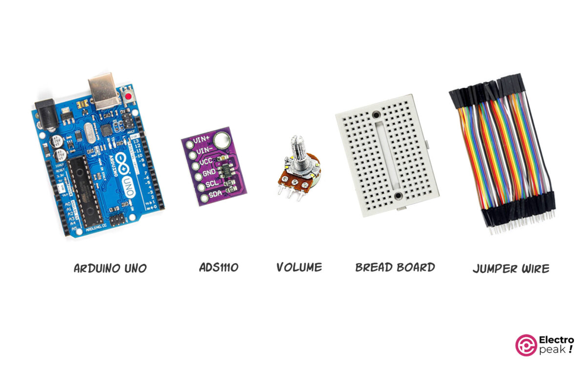
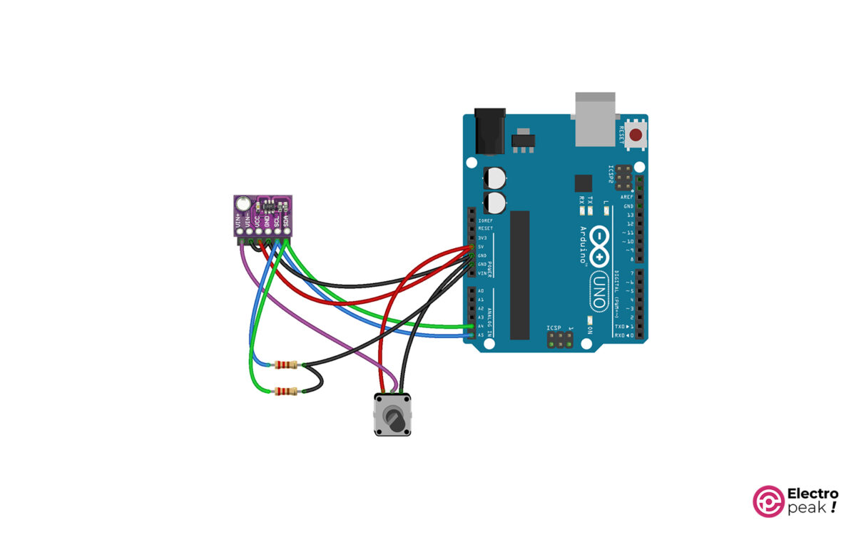
In our project, we will use a potentiometer output—2 to 10KΩ— as the input data for the ADS1110 module. We’ll also need PULL-UP resistors—1 to 10KΩ— to interface the module.

ADS1110 Pinout

The ADS1110 module has 6 pins:
VIN: Module power supply
GND: Ground
SDA: For I2C protocol
SCL: For I2C protocol
VIN-: Negative power supply pin
VIN+: Positive power supply pin

ADS1110 Pinout

Required Materials

Interfacing ADS1110 Module with Arduino

Step 1: Wiring

Connect the wires as shown below.

ADS1110 Interface Circuit

Step 2: Set Up Arduino IDE

In the Arduino IDE software, select the desired board type and port as shown below.

Arduino IDE Settings (1)
Arduino IDE Settings (2)

Step 3: Code

Upload the following code to your Arduino.

#include "Wire.h"
#define ads1110 0x48
float voltage, data;
byte highbyte, lowbyte, configRegister;
void setup()
{
 Serial.begin(9600);
 Wire.begin();
}
void loop()
{
 Wire.requestFrom(ads1110, 3);
 while(Wire.available()) // ensure all the data comes in
 {
 highbyte = Wire.read(); // high byte * B11111111
 lowbyte = Wire.read(); // low byte
 configRegister = Wire.read();
 }

 data = highbyte * 256;
 data = data + lowbyte;
 Serial.print("Data >> ");
 Serial.println(data, DEC);
 Serial.print("Voltage >> ");
 voltage = data * 2.048 ;
 voltage = voltage / 32768.0;
 Serial.print(voltage, DEC);
 Serial.println(" V");
 delay(1000);
}

Code Explanation

#include "Wire.h"
#define ads1110 0x48
float voltage, data;
byte highbyte, lowbyte, configRegister;

First, we call the I2C-related library and then find the I2C address of the module. To find the address, go to File –> Wire –> Examples, and run the I2C_scanner example; the Serial Monitor window will display the address. Next, we define the required variables.

Wire.requestFrom(ads1110, 3);
 while(Wire.available()) // ensure all the data comes in
 {
 highbyte = Wire.read(); // high byte * B11111111
 lowbyte = Wire.read(); // low byte
 configRegister = Wire.read();
 }

Here, the data sent by the module is stored in three variables.

data = highbyte * 256;
 data = data + lowbyte;
 Serial.print("Data >> ");
 Serial.println(data, DEC);
 Serial.print("Voltage >> ");
 voltage = data * 2.048 ;
 voltage = voltage / 32768.0;
 Serial.print(voltage, DEC);
 Serial.println(" V");
 delay(1000);

Finally, we perform the necessary calculations, as mentioned in the module datasheet, to convert the received data into the desired format. After running the code, you can view the desired output in the Serial Monitor window, displaying the 16-bit data and corresponding voltage values.

ADS110 (Serial Monitor)

Important Tips for Troubleshooting

• Check the circuit connections.
• Verify the I2C address.
• Select the resistors according to the specified values.

Liked What You See?​
Get Updates And Learn From The Best​

Leave a Reply

Your email address will not be published. Required fields are marked *