Overview
A potentiometer is a device that can change its resistance by moving a contact along a fixed resistor. It has three terminals: one connected to each end of the resistor and one connected to the movable contact. By adjusting the position of the contact, the potentiometer can divide the input voltage into different output voltages [Read more in Wikipedia].
Potentiometers work by creating a voltage drop across the resistor that is proportional to its length. For example, if the input voltage is 10V and the resistor has a uniform resistance of 1Ω per cm, then moving the contact 5cm from one end will create a 5V output voltage.
Potentiometers, or pots for short, have different shapes and uses in your daily life, such as regulating the sound level of the radio.
Potentiometers also have two types: mechanical and digital. We manually adjust the potentiometer in the mechanical type by screws. In the digital model, however, we use programming and software to adjust it.
What You Will Learn
The purpose of this tutorial is to learn how to use an important component called a potentiometer. First, we explain the principles and how they work, and their types, and then we do a project in order to understand the issues mentioned.
At the end of this tutorial you will be familiar with the following:
- How potentiometer works
- Types of potentiometers
- Perform a simple test to better understand the concepts presented
How A Potentiometer Works?
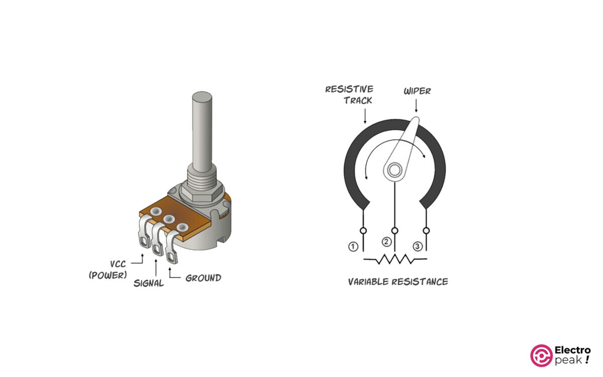
Each potentiometer has 3 pins: two terminal pins to connect to 0 and VCC; and the middle pin as the output. In fact, by rotating the potentiometer, you change the voltage of the middle pin.
The main structure of potentiometers is as follows:
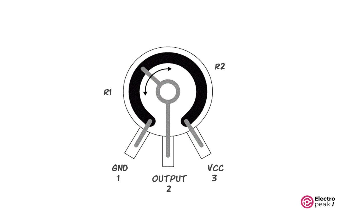
The total resistance of a potentiometer is the resistance between the GND and VCC pins. As you can see, R1 is the resistance between GND and OUTPUT and R2 is the resistance between OUTPUT and VCC. The sum of R1 and R2 is always equal to the total resistance of the potentiometer.
You saw an example of a structural and real form of a potentiometer. The potentiometer is represented by the following symbol in electronic circuits:
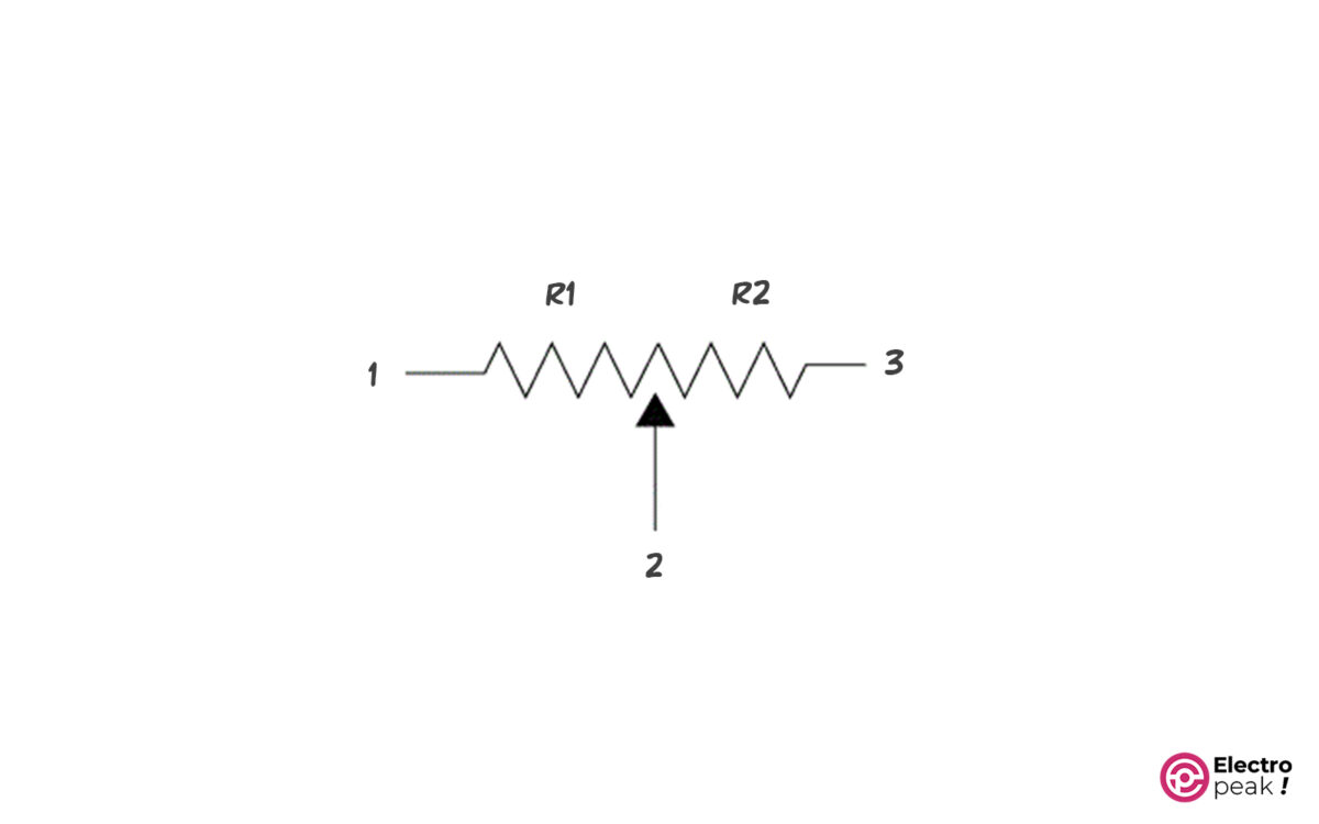
Its symbol is exactly like normal resistors, except that it also has an adjustable end (pin 2) that can be changed from point 1 to point 3. Pins 1 and 3 are the fixed pins of the potentiometer and pin 2 is the variable one.
Reading potentiometer values is also very simple. For example, the number 103 on a potentiometer indicates a total resistance of 10KΩ. Or 252, for instance, means 2.5KΩ.
Potentiometer Applications
Generally, we use a potentiometer for two purposes:
• As a voltage reference: As the potentiometer rotates, the voltage of its output pin changes from 0 to VCC. We can calculate the voltage value with a simple voltage divider equation:
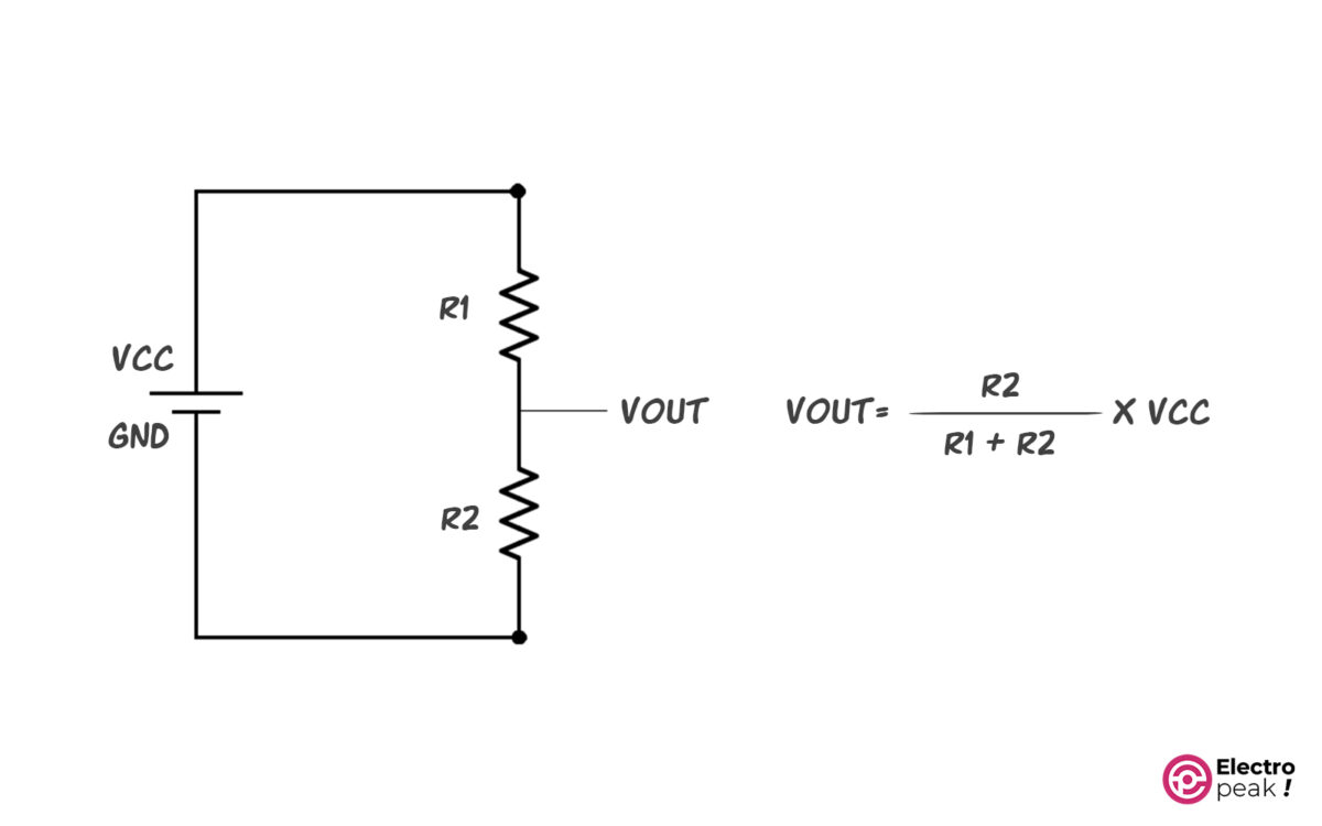
For example, the voltage of this pin should range from 0 to 5 volts for the Arduino analog input.
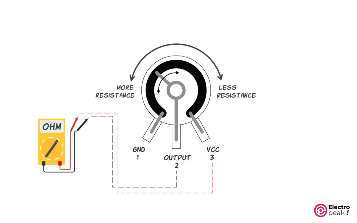
• As a variable resistor: For example, if you have a 10K potentiometer, the resistance between pins 1 and 3 is 10KΩ.
To understand this more accurately, you can connect the two pins 2 and 3 of a potentiometer to the multimeter and observe its variable resistance by rotating the middle pin. This way you will see that this resistance varies from 0 to 10KΩ.
Different Types of Potentiometers
Potentiometer Types Based on Applications
Although all potentiometers operate on the same principles, different models have different applications in electronic circuits.
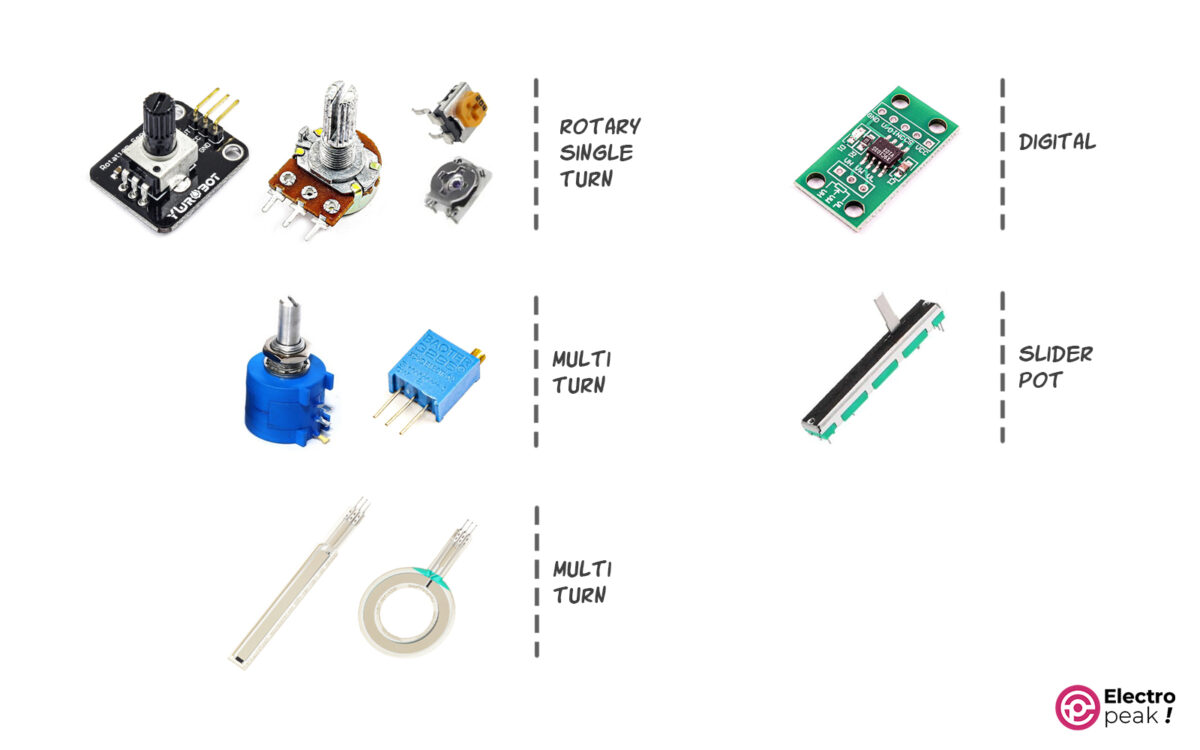
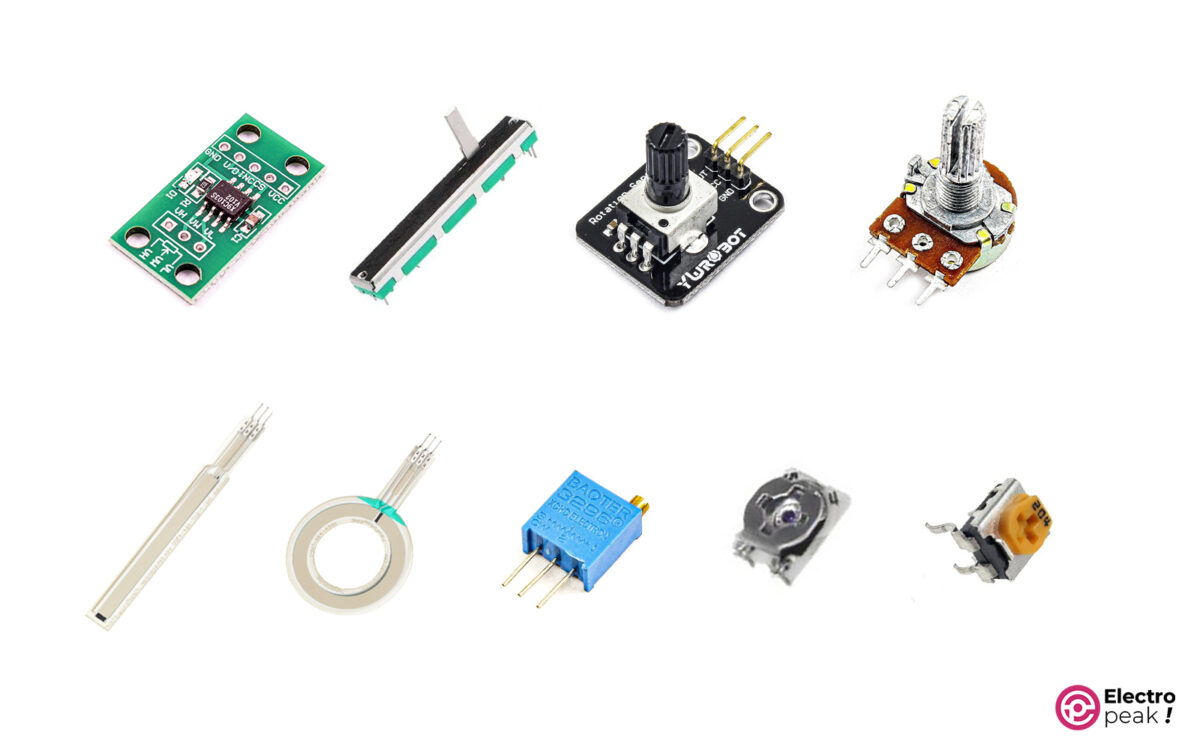
As shown above, the types of these potentiometers in terms of application are:
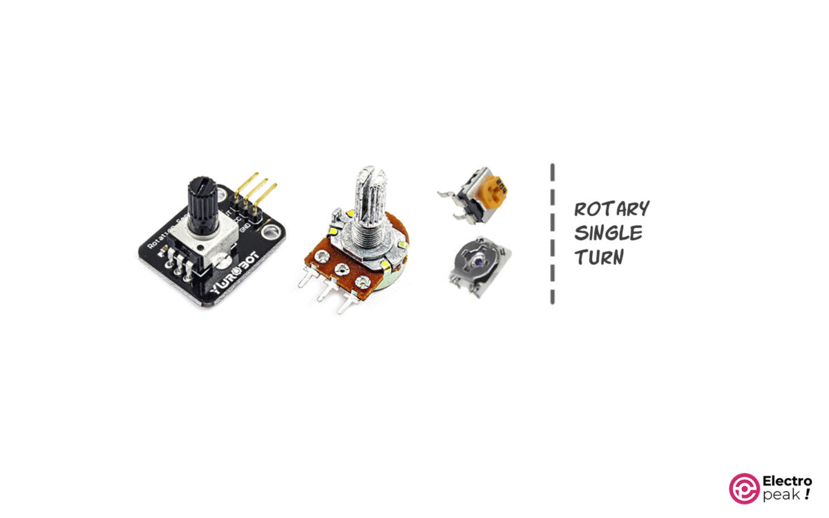
Single-Turn Potentiometers
These potentiometers are often less than one round and have different models as shown in the photo.
Features:
• Their sizes change depending on the power required.
• They have low accuracy due to the small number of rounds.
• Available in both DIP and SMD.
• They play an important role in electronic circuits and are widely used.
Applications:
• Used in power supplies to regulate current and voltage
• To adjust and limit short circuit current
• Speed control of DC fans and motors
• Amplifiers
• Control systems
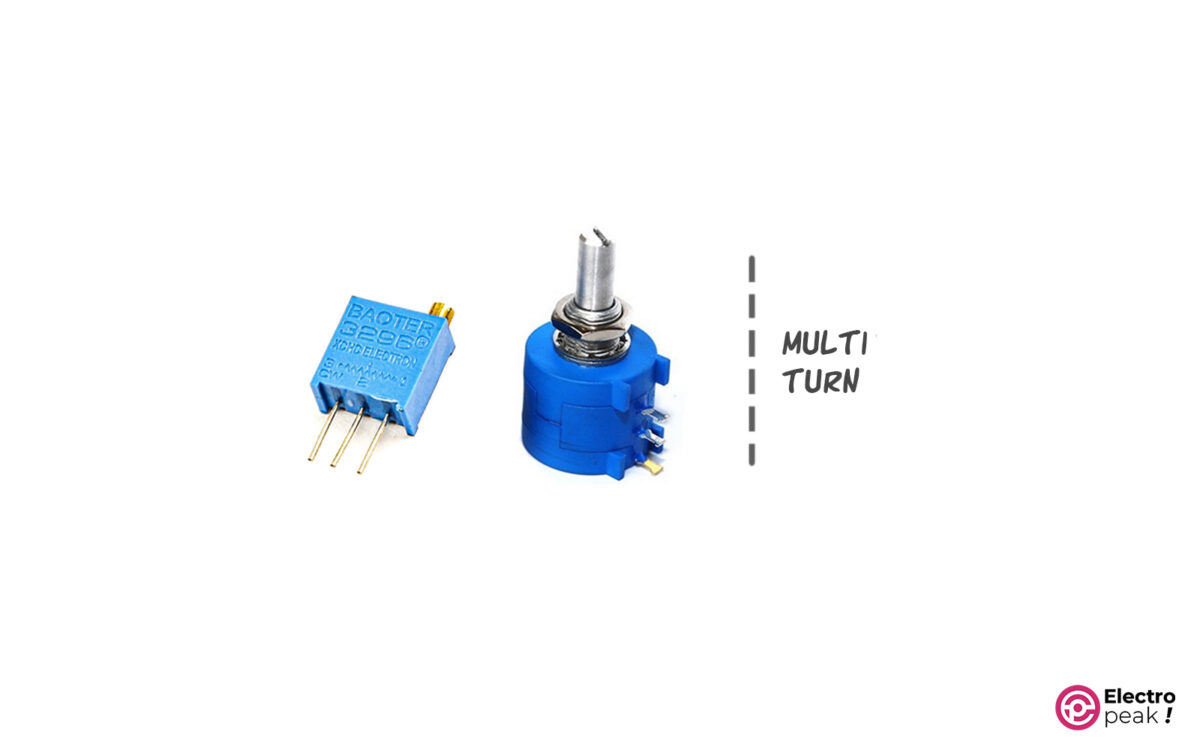
Multi-Turn Potentiometers
The number of turns on these models is more than one. So they can give you higher accuracy of resistance changes. They have two models for various applications: low power and high power.
Application:
• Adjust the current and voltage of electronic converters
• Adjust LCD contrast
• Used in cases where you need high precision
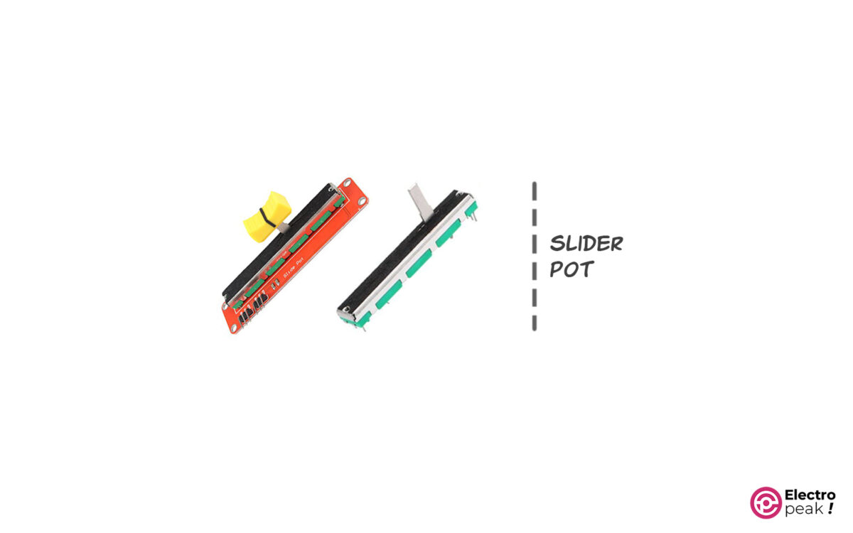
Slider Potentiometers
As their name and picture suggest, the resistance value of these potentiometers changes with the linear and direct motion of the moving pin.
In some cases, you might need to change the resistance in a linear way, such as:
• Equalizers
• Increase and decrease volume in audio systems
• Used in toys (as reducing and increasing speed by accelerator pedal or brake)
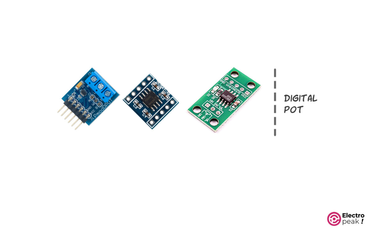
Digital Potentiometers
Sometimes you need to have a variable resistor adjustable by software. There are a variety of modules and ICs for this purpose:
• X9C104
• X9C103S
• DS3502
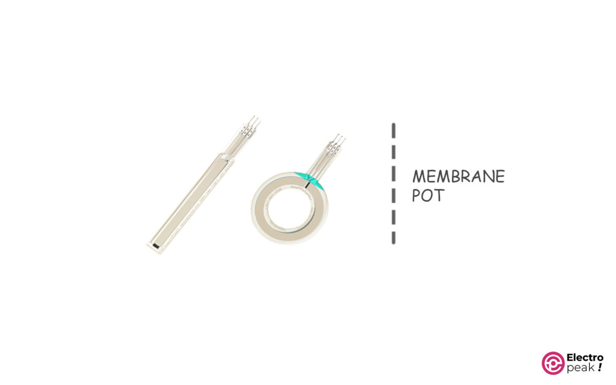
Membrane Potentiometers
These potentiometers are very thin and we use them for specific applications. The resistance of this type of potentiometer can be adjusted by the user’s hand pressure. That is, by moving your finger on the surface, the amount of output resistance changes.
Linear and Nonlinear Potentiometers
There are two types of potentiometers: linear and nonlinear. In the linear type, the resistance changes are linear in terms of the clamp position. In the nonlinear type, however, these changes are nonlinear. In addition, the letter B on potentiometers indicates linearity and the letter A indicates nonlinearity.
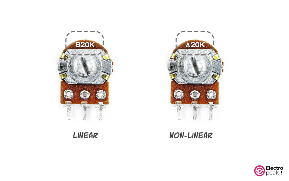
Linear Potentiometers
As mentioned, in these potentiometers, the resistance change due to the rotation or clamp position is linear. That is, changes in low resistances and high resistances are equal. For example, if the clamp is in the middle, the output resistance is half the total resistance.
Most potentiometers on the market are linear.

Nonlinear Potentiometers
In these potentiometers, the resistance change due to the rotation or clamp position is nonlinear. Resistance changes with a steep slope either at the beginning of the movement or at the end. These changes are logarithmic.

Required Materials
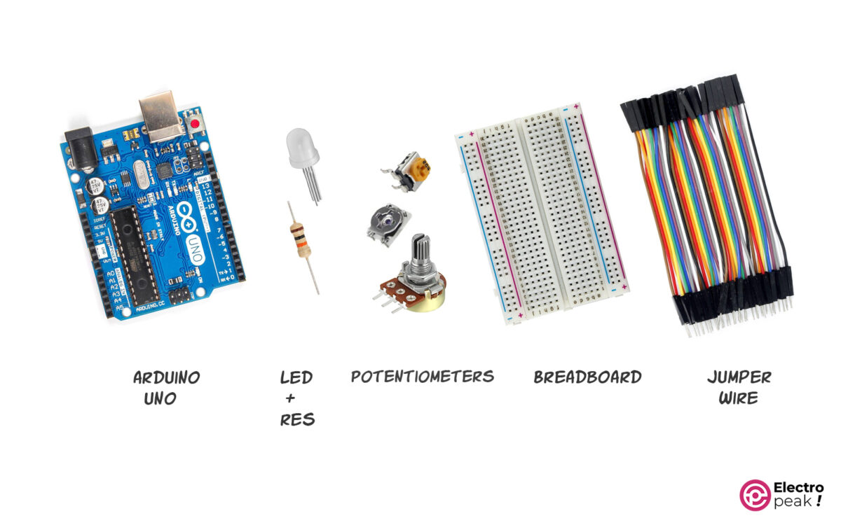
Hardware Components
Testing and Comparing Potentiometers
In the following, to test and compare some of the potentiometers introduced above, we have used three of them:
1- 2KΩ Volume
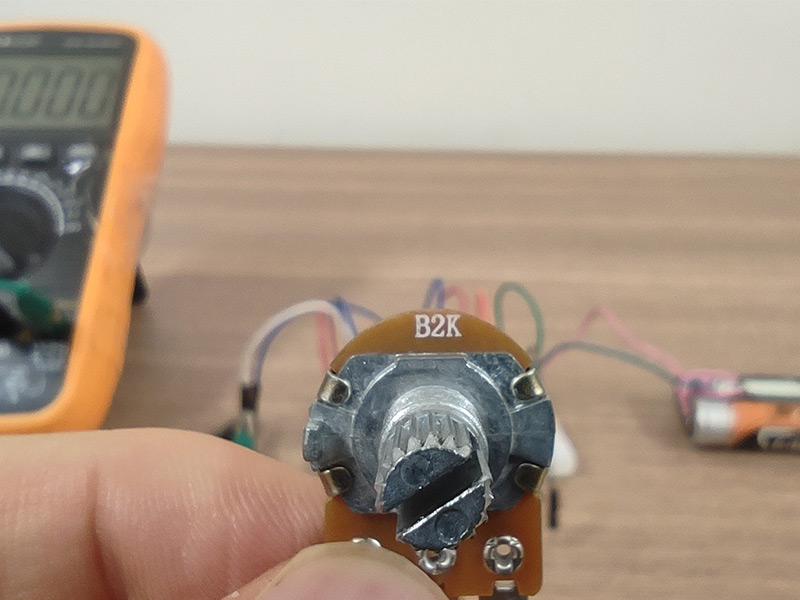
2- 1MΩ Multi-Turn Trimmer Potentiometer
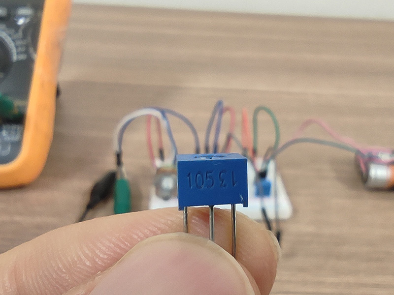
3- 1KΩ Multi-Turn Trimmer Potentiometer
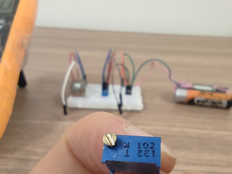
Step 1: Circuit
First, prepare the following circuit for the first test.
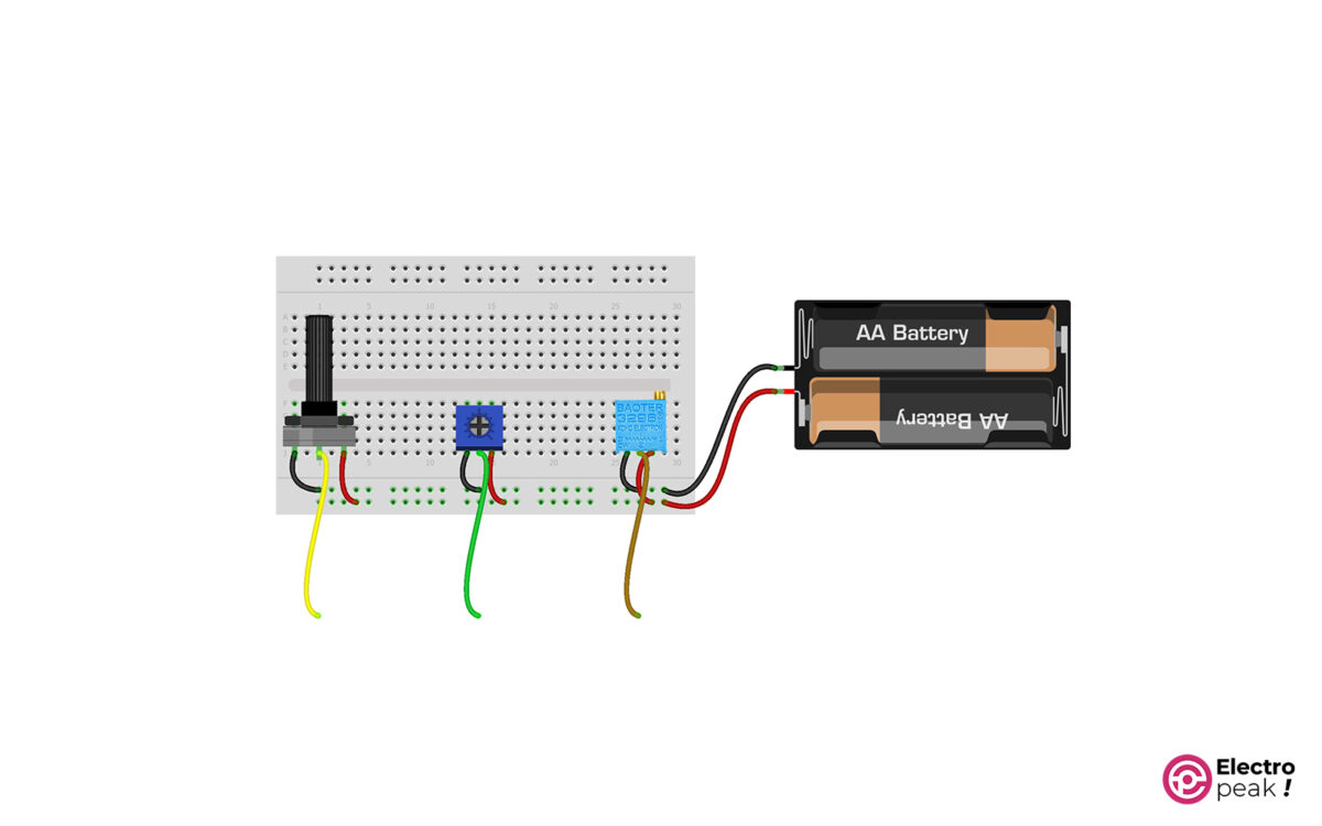
We have used two lithium batteries in series for this test.
We have connected pins 1 and 3 of each potentiometer to the positive and negative pins of the battery. This voltage is about 7.4 volts.
The variable voltage is generated by pin #2. So, we connect a wire to each of these pins to measure their voltage.
Step 2: Test and Compare Voltage
It was mentioned that one of the applications of potentiometers in circuits is to generate different voltage references. That’s why we tested and compared three potentiometers that are widely used in electronic circuits.
First, we supply the potentiometers with two lithium batteries in series, providing 7.4 volts. Then, we check how the voltage between the Ground and pin #2 changes for all potentiometers by rotating them.
As you can see in the video above, we first measured the battery reference voltage. The exact voltage value is 7.43 volts.
In the next steps, we observe the voltage changes in 3 potentiometers, respectively. And by rotating the potentiometer, we increase the voltage from 0 to the maximum.
2KΩ Volume:
• Minimum voltage: 0.08 volts
• Maximum voltage: 7.15 volts
• Accuracy: low
1MΩ Multi-Turn Trimmer Potentiometer:
• Minimum voltage: 0.00 volts
• Maximum voltage: 7.25 volts
• Accuracy: low
1KΩ Multi-Turn Trimmer Potentiometer:
• Minimum voltage: 0.04 volts
• Maximum voltage: 7.4 volts
• Accuracy: high
Step 3: Test and Compare the Accuracy of Resistors
It was stated that the second application of potentiometers is to use them as variable resistors.
In the following experiment, we first measure the total resistance of potentiometers–the resistance between pins 1 and 3. Then we connect one end of the multimeter to GND and the other end to pin 2. Next, we start rotating the potentiometer to see how the resistance changes.
How to Use a Potentiometer with Arduino
In the previous sections, we got familiar with the structure and different types of potentiometers. Now, we are going to see how we can use them as analog input in Arduino.
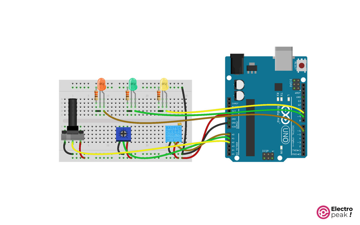
Here, we control the light of three LEDs using the three potentiometers. Also, we simultaneously display the voltage of the middle pins of each potentiometer on the Serial Monitor.
In the first step, we prepare the circuit.
Step 1: Circuit
Prepare the circuit as follows. Connect the outputs–middle pins–of the three potentiometers to pins A0, A1, and A2, respectively.
Step 2: Code
After preparing the circuit above, connect your Arduino Board to the computer and upload the following code on it.
/*
 Potentiometer
 made on 23 Jan 2022
 by Amir Mohammad Shojaee @ Electropeak
 Home
*/

int orange_LED = 6;
int green_LED = 9;
int yellow_LED = 10;

void setup() {
 // initialize serial communication at 9600 bits per second:
 Serial.begin(9600);
 pinMode(orange_LED, OUTPUT);
 pinMode(green_LED, OUTPUT);
 pinMode(yellow_LED, OUTPUT);
}


void loop() {

 int orange_pot = analogRead(A2); // read the input on analog pin 0:
 float orange_voltage = orange_pot * (5.0 / 1023.0); // Convert the analog reading (which goes from 0 - 1023) to a voltage (0 - 5V):
 int x = map(orange_pot, 0, 1023, 0, 255);
 analogWrite(orange_LED, x); // print out the value you read:


 int green_pot = analogRead(A1); // read the input on analog pin 0:
 float green_voltage = green_pot * (5.0 / 1023.0); // Convert the analog reading (which goes from 0 - 1023) to a voltage (0 - 5V):
 int y = map(green_pot, 0, 1023, 0, 255);
 analogWrite(green_LED, y); // print out the value you read:


 int yellow_pot = analogRead(A0); // read the input on analog pin 0:
 float yellow_voltage = yellow_pot * (5.0 / 1023.0); // Convert the analog reading (which goes from 0 - 1023) to a voltage (0 - 5V):
 int z = map(yellow_pot, 0, 1023, 0, 255);
 analogWrite(yellow_LED, z); // print out the value you read:

 Serial.print("orange_voltage:");
 Serial.print(orange_voltage);

 Serial.print(" green_voltage:");
 Serial.print(green_voltage);

 Serial.print(" yellow_voltage:");
 Serial.println(yellow_voltage);

 delay(300);
}
Note the following:
• We have used three PWM pins of 6, 9, and 10 to adjust the light of the LEDs.
• When running the program, the voltage of the middle pins of the potentiometers is displayed on the Serial Monitor.
Step 3: Output
After uploading the code above, open the Serial Monitor. By rotating the potentiometers, the output displayed on the Serial Monitor as well as the light of the LEDs should change as shown in the following video.
As you can see:
• The accuracy of changes for the yellow LED (multi-turn potentiometer) is higher.
• The minimum and maximum voltages are approximately 0 and 5 volts for each potentiometer.
