
Overview
What You Will Learn
- Introduction to the ESP32 and its applications
- Installing the ESP32 on Arduino IDE
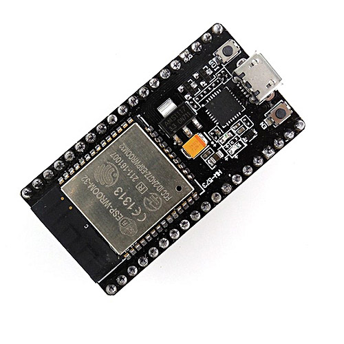
What is ESP32?
The ESP32 Module Features
| Working Voltage | 2.2 to 3.6 volts |
|---|---|
| Average Current | Around 80 mA |
| Maximum Current | 500 mA |
| Input/Output Pins | 32(The ESP32 chip has 48 I/O pin,s. But the module has only 28 accessible pins.) |
| ADC(Analog to Digital Converter) | 18 channels of 12 bits |
| DAC(Digital to Analog Converter) | 2 channels of 8 bits |
| UART(Serial Communication) | 3 |
| PWM | 32 |
| SPI Interface | 4 |
| I2C Interface | 2 |
| I2S Interface (to connect audio devices) | 2 |
| Capacitance TouchPads Pins | 10 |
| Memory Card Interface | 1 |
| CAN Interface | 1 |
| Temperature Sensor | 1 |
Note
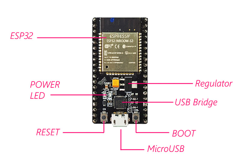
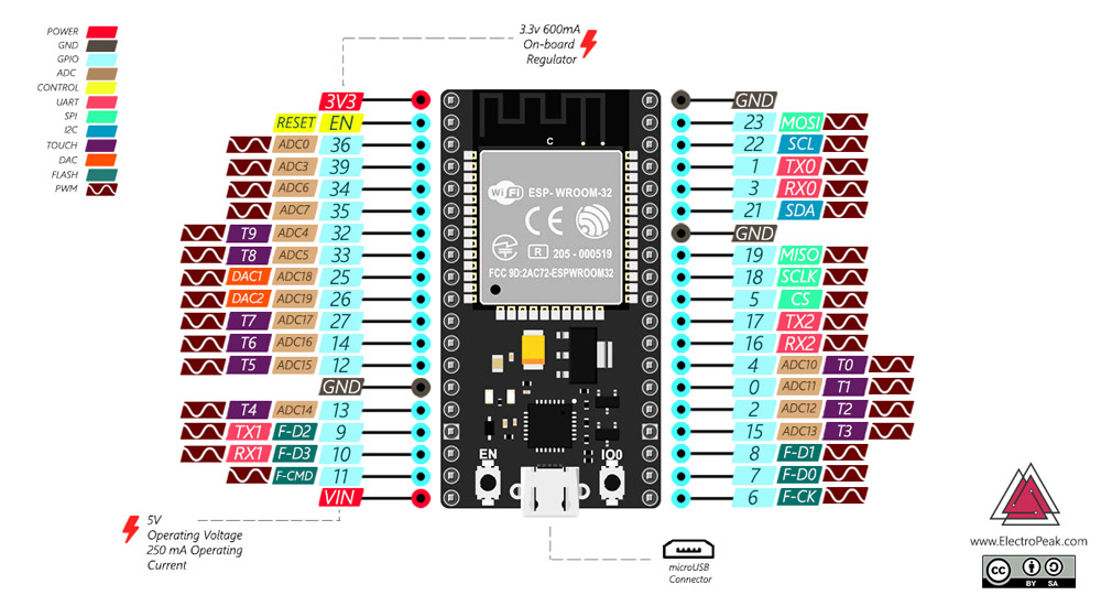
The ESP32 Module Pinout
Although the ESP32 has fewer pins than commonly used processors, you won’t face any problem with multiplexing multiple functions on a pin.
Warning
The voltage level of the ESP32 pins is 3.3 volts. If you want to connect ESP32 to other devices that operate at 5–volts voltage, you should use a level shifter to convert the voltage level.
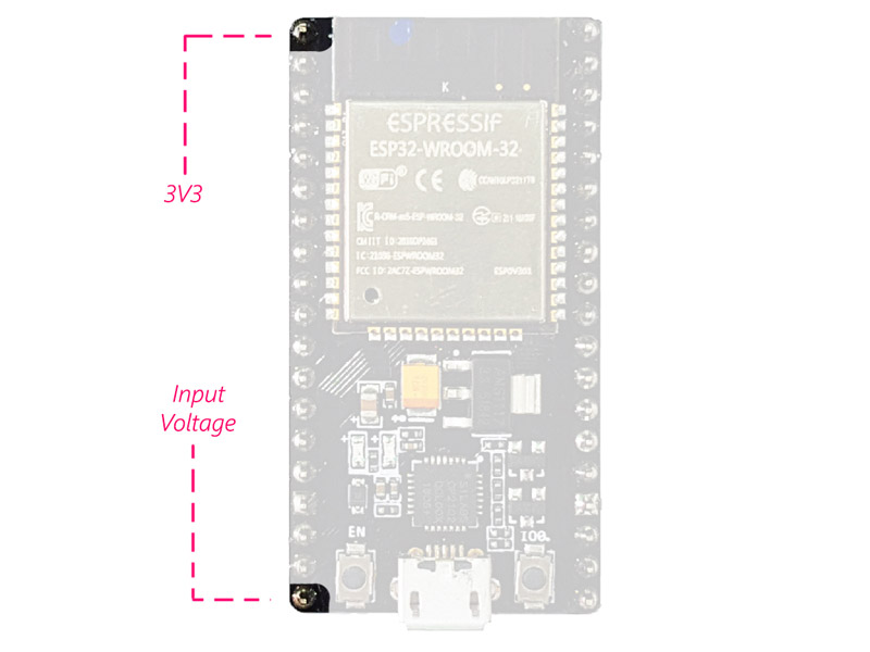
Supply Pins:
The module has two 5V and 3.3V power supply pins. You can use these two pins to supply other devices and modules.
GND Pin:
The module has 3 pins for its ground.

Enable Pin (EN):
This pin is used to enable and disable the module. It should be HIGH to enable the module and must be LOW to disable it.
Input/Output Pins (GPIO):
You can use the 32 GPIO pins to communicate with the LEDs, switches, and other input/output devices.
You can pull-up or pull-down these pins internally.
Note
ADC:
You can use the 16 ADC pins on this module to convert analog voltages (output of some sensors) to digital. Some of these converters are connected to the internal amplifier and are able to measure small voltages with high precision.

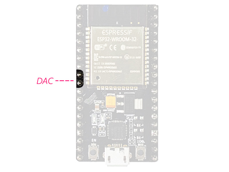
DAC:
The ESP32 module has two digital to analog converters with 8 bits accuracy.
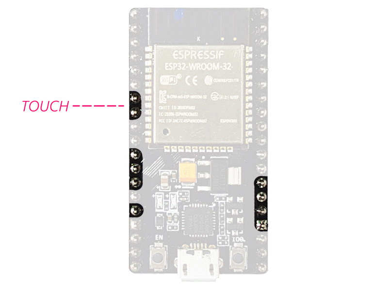
Touchpads:
There are 10 pins on the ESP32 module that are sensitive to capacitor changes. You can connect these pins to some pads (the pads on the PCB) and use them as touch switches.
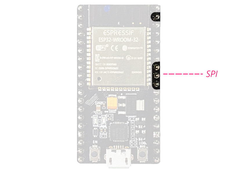
SPI:
There are two SPI interfaces on this module that you can use to connect the display, the SD / microSD memory card module, external flash memory, and more.
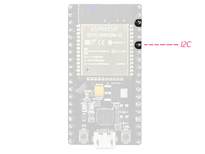
I2C:
SDA and SCL pins are used for I2C communication.
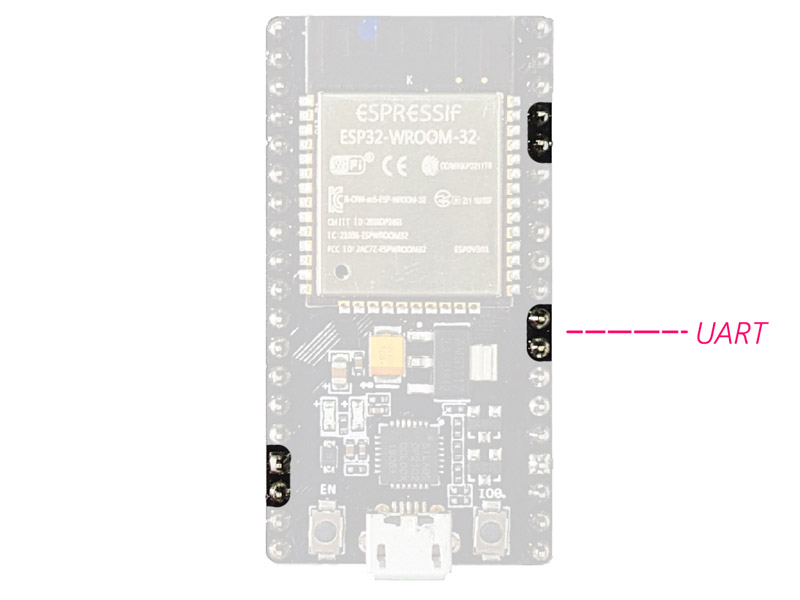
Serial Communication (UART):
There are two UART serial interfaces on this module. Using these pins, you can transfer information up to 5Mbps, between two devices. UART0 has also CTS and RTS bases.
PWM:
Almost all of the ESP32 input/output pins can be used for PWM (Pulse Width Modulation). Using these pins you can control the motors, LEDs light and color and so on.
The ESP32 Module Modes
The ESP32 chip has 5 modes:
Active mode:
In this case, all parts of the Wi-Fi and Bluetooth transmitter and receiver are active. In this case, the current consumption is between 80 and 260 mA.
Modem-sleep mode:
The processor is still active, but the Wi–Fi and Bluetooth are disabled. The current consumption is between 3 and 20 mA, in this case.
Light-sleep mode:
The main processor stops working, but the RTC unit and the ULP processor unit are still active. The current consumption is about 0.8 mA.
Deep-sleep mode:
Only the RTC unit is active. In this case, the data of Wi-Fi and Bluetooth communications are stored in the RTC’s memory. The current consumption is between 10 and 150 μA in this mode.
Hibernation mode:
All units are disabled, except for an RTC timer for the clock and some I / O pins connected to the RTC. The RTC timer or the connected pins can wake the chip up from this state. The current consumption is about 2.5 μA in this case.
For more information, you can check the module datasheet.
ESP32 chip and Module Datasheet
The datasheet of ESP32 module and its chipset can be downloaded from the following links.
ESP32 VS. ESP8266
| ESP8266 NodeMcu | ESP32 DEV Module | |
|---|---|---|
| Power | 3.3V | 3.3V |
| CPU | Tensilica L106 32-bit | Xtensa® Dual-Core 32-bit LX6 |
| Bluetooth | Do not have | Compliant with Bluetooth v4.2 BR/EDR and BLE specification |
| GPIO | 17 | 32 |
| Flash size | Up to 16MB | Up to 16MB |
| ADC | 10 bit | 12 bit |
| DAC | Do not have | 2 * 8bit |
| UART | 2 | 2 |
Required Materials
Hardware Components
Software Apps
Installing the ESP32 on Arduino IDE
Note
First Step: Downloading the required files from the GitHub
Download the ESP32 Arduino Core from its GitHub account. You can use the direct download link as well.
https://github.com/espressif/arduino-esp32/archive/master.zip
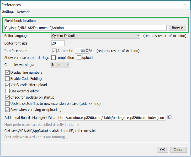
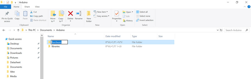
Second Step: Move the file to Arduino sketchbook location
The Arduino sketchbook is located in My Documents by default. To find the exact path of your sketchbook, check the preferences from the File menu.
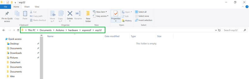
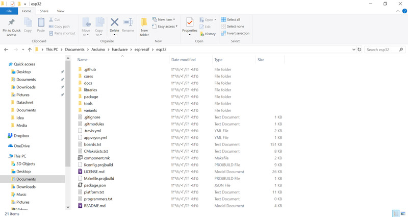
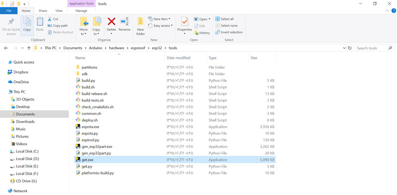
Third Step: Run the get.exe
To install ESP32 on the Arduino software, you need to install the Xtensa GNU compiler collection on your system. Go to esp32> tools and run the get.exe file.

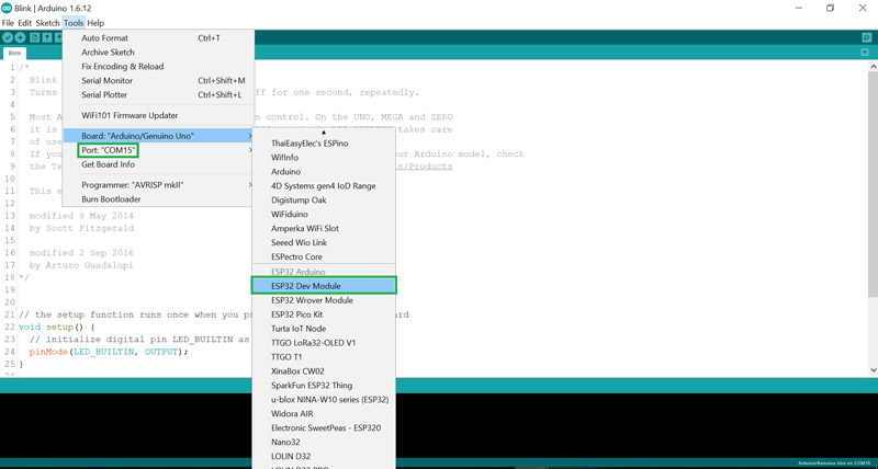
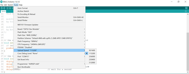
Uploading the Codes on ESP32 Using Arduino IDE
Tip
void setup() {
  pinMode(2, OUTPUT);
}

void loop() {
  digitalWrite(2, HIGH);   // turn the LED on (HIGH is the voltage level)
  delay(1000);                       // wait for a second
  digitalWrite(2, LOW);    // turn the LED off by making the voltage LOW
  delay(1000);                       // wait for a second
}
Troubleshooting
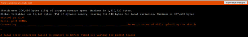
2.Press and hold the Boot button on your board.
3.Click on the Upload option.
4.When you see the message Writing at 0x00001000 … (100%), remove your finger from the Boot button.
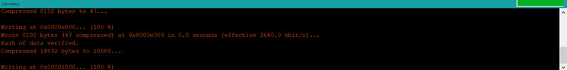
5.You must see the Done uploading message when the uploading is finished.
What’s Next?
- Create an HTTP page and control an LED through a webpage.
- Control the LED using Bluetooth communication. (You can use Bluetooth terminals to do this.)

Comments (13)
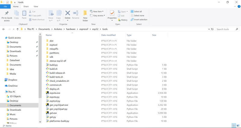
A couple of things you’ve missed out. After running Get.exe you say that some files must be moved in to the tools folder. Great, but where from? Secondly don’t you have to press one of the buttons on the ESP32 to set it into the right mode first time out?
Hi. Thanks to read my tutorial. Nothing was missed. Those files are created automatically and you don’t need to copy them manually.
For the type of module that I used, there is no need to use buttons to set it to the right mode.
The best totorial that I already get.
Thanks!
Hats off to you. Very well explained in simple language with lots of illustrations. Thank you so much
Excellent tutorial. Very simple language with adequate illustrations . Hats off to you.
You’re so welcome. We’re so glad you enjoyed it.
Thanks, it is easy to understand
You’re quite welcome.
I’m so very grateful for your abundant use of images to ensure readers get what you’re pointing out.
I just got introduced to ESP32 and found it to be the best so far among the arduino modules. With both Bluetooth and WiFi connectivity, it’s complete!
Thanks.
Yes, it offers a lot more features than ordinary Arduino boards like arduino uno. And you’re so welcome. We’re glad if we could be of any help.
Hi and thanks for the tutorial. I am having one problem though. Using the Github link to download Esp32 Arduino Core. When i download the zip file it wont unzip…bad file.
Can you please help me with this?
Tony Wheat
Hi… You’re so welcome!
Downloading the ESP32 Arduino Core is actually an out of date way to install ESP32 in Arduino IDE. There is a much faster and more efficient way to do that. You can use the following tutorial for more details:
https://electropeak.com/learn/installing-the-esp32-board-in-arduino-ide-windows-mac-os-x-linux/