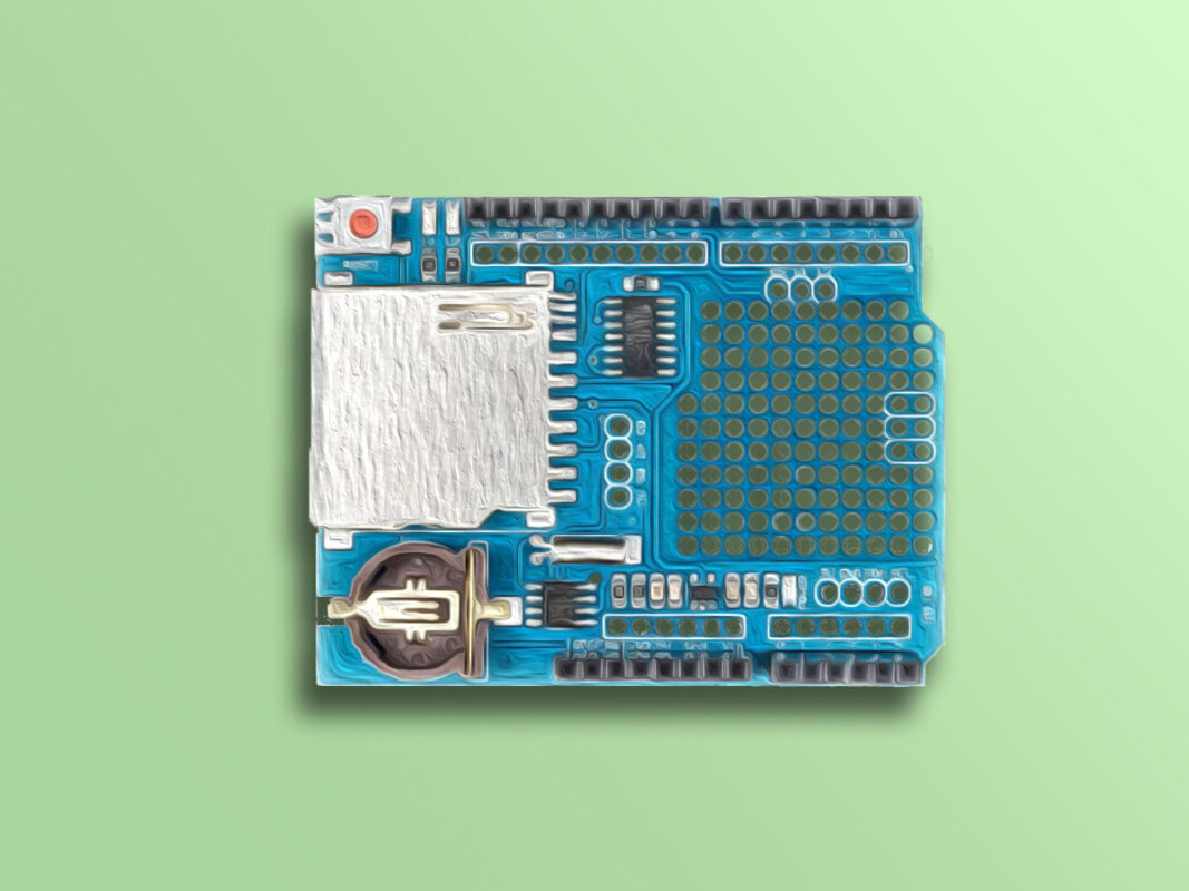
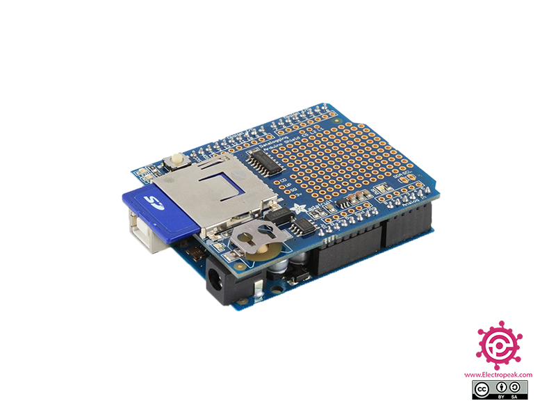
Arduino Data Logger Shield Features
The Arduino data logger shield can be used to make a connection between an Arduino and an SD card. In fact, this module can be used to store Arduino data. It is very suitable for storing data when the Arduino power supply suddenly shuts down. This module also has a DS1307 module as RTC for keeping time and date. The communication protocol for RTC is I2C and for SD card is SPI.
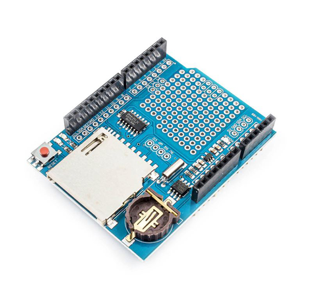
Arduino Data Logger Shield Pinout
This module is placed exactly on Arduino and its pins become the pins of Arduino.
Required Materials
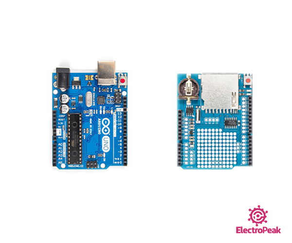
Hardware Components
Software Apps
Interfacing Arduino Data Logger Shield
Step 1: Circuit
The following circuit shows how you should connect Arduino to this module. Connect wires accordingly.
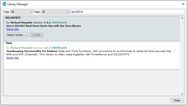
Step 2: Installing Library
Go to Library manager and install the DS1307RTC library.
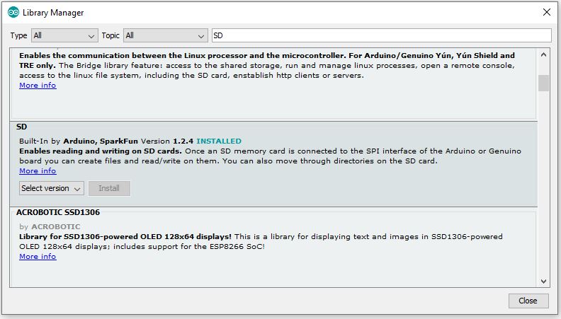
Then install the SD library.
Tip
If you need more help with installing a library on Arduino, read this tutorial: How to Install an Arduino Library
Step 3: Code
Upload the following code to Arduino. After that, open the Serial Monitor.
   /*
Modified on Nov 24, 2020
Modified by MehranMaleki from Arduino Examples
Home
*/

#include "SD.h"
#include <Wire.h>
#include <DS1307RTC.h>


const char *monthName[12] = {
  "Jan", "Feb", "Mar", "Apr", "May", "Jun",
  "Jul", "Aug", "Sep", "Oct", "Nov", "Dec"
};
tmElements_t tm;


// A simple data logger for the Arduino analog pins
#define LOG_INTERVAL  1000 // mills between entries

// how many milliseconds before writing the logged data permanently to disk
// set it to the LOG_INTERVAL to write each time (safest)
// set it to 10*LOG_INTERVAL to write all data every 10 datareads, you could lose up to
// the last 10 reads if power is lost but it uses less power and is much faster!
#define SYNC_INTERVAL 1000 // mills between calls to flush() - to write data to the card
uint32_t syncTime = 0; // time of last sync()

#define ECHO_TO_SERIAL   1 // echo data to serial port
#define WAIT_TO_START    0 // Wait for serial input in setup()


// The analog pins that connect to the sensors
#define voltPin A0           // analog A0


// for the data logging shield, we use digital pin 10 for the SD cs line
const int chipSelect = 10;

// the logging file
File logfile;


void setup(void)
{
  Serial.begin(9600);
  while (!Serial) ; // wait for serial
  delay(2000);


  bool parse=false;
  bool config=false;

  // get the date and time the compiler was run
  if (getDate(__DATE__) && getTime(__TIME__)) {
    parse = true;
    // and configure the RTC with this info
    if (RTC.write(tm)) {
      config = true;
    }
  }

  if (parse && config) {
    Serial.print("DS1307 configured Time=");
    Serial.print(__TIME__);
    Serial.print(", Date=");
    Serial.println(__DATE__);
  } else if (parse) {
    Serial.println("DS1307 Communication Error :-{");
    Serial.println("Please check your circuitry");
  } else {
    Serial.print("Could not parse info from the compiler, Time=\"");
    Serial.print(__TIME__);
    Serial.print("\", Date=\"");
    Serial.print(__DATE__);
    Serial.println("\"");
  }


#if WAIT_TO_START
  Serial.println("Type any character to start");
  while (!Serial.available());
#endif //WAIT_TO_START


  // initialize the SD card
  Serial.print("Initializing SD card...");
  // make sure that the default chip select pin is set to
  // output, even if you don't use it:
  pinMode(10, OUTPUT);

  // see if the card is present and can be initialized:
  if (!SD.begin(chipSelect)) {
    Serial.println("Card failed, or not present");
    // don't do anything more:
    return;
  }
  Serial.println("card initialized.");

  // create a new file
  char filename[] = "LOGGER00.CSV";
  for (uint8_t i = 0; i < 100; i++) {
    filename[6] = i/10 + '0';
    filename[7] = i%10 + '0';
    if (! SD.exists(filename)) {
      // only open a new file if it doesn't exist
      logfile = SD.open(filename, FILE_WRITE);
      break;  // leave the loop!
    }
  }

  if (! logfile) {
    error("couldnt create file");
  }

  Serial.print("Logging to: ");
  Serial.println(filename);


   // If you want to set the aref to something other than 5v
  //analogReference(EXTERNAL);
}


void loop(void)
{

  // delay for the amount of time we want between readings
  delay((LOG_INTERVAL -1) - (millis() % LOG_INTERVAL));


  // log milliseconds since starting
  uint32_t m = millis();
  logfile.print("Miliseconds Since Start: ");           // milliseconds since start
  logfile.println(m);
#if ECHO_TO_SERIAL
  Serial.print("Miliseconds Since Start: ");
  Serial.println(m);         // milliseconds since start
#endif

  delay(2000);


  if (RTC.read(tm)) {
    Serial.print("Ok, Time = ");
    print2digits(tm.Hour);
    Serial.write(':');
    print2digits(tm.Minute);
    Serial.write(':');
    print2digits(tm.Second);
    Serial.print(", Date (D/M/Y) = ");
    Serial.print(tm.Day);
    Serial.write('/');
    Serial.print(tm.Month);
    Serial.write('/');
    Serial.print(tmYearToCalendar(tm.Year));
    Serial.println();
  } else {
    if (RTC.chipPresent()) {
      Serial.println("The DS1307 is stopped.  Please run the SetTime");
      Serial.println("example to initialize the time and begin running.");
      Serial.println();
    } else {
      Serial.println("DS1307 read error!  Please check the circuitry.");
      Serial.println();
    }
    delay(9000);
  }
  delay(2000);


int voltReading = analogRead(voltPin);
  delay(10);
  // converting that reading to voltage, for 3.3v arduino use 3.3
  float voltage = (voltReading * 5.0) / 1024.0;

  logfile.print("Data We Read from Analog Pin: ");
  logfile.print(voltReading);
  logfile.print(", ");
  logfile.print("Calculated Voltage: ");
  logfile.println(voltage);
#if ECHO_TO_SERIAL
  Serial.print("Data We Read from Analog Pin: ");
  Serial.print(voltReading);
  Serial.print(", ");
  Serial.print("Calculated Voltage: ");
  Serial.println(voltage);
#endif //ECHO_TO_SERIAL

  delay(1000);

  // Now we write data to disk! Don't sync too often - requires 2048 bytes of I/O to SD card
  // which uses a bunch of power and takes time
  if ((millis() - syncTime) < SYNC_INTERVAL) return;
  syncTime = millis();
  logfile.flush();
}

void error(char *str)
{
  Serial.print("error: ");
  Serial.println(str);

  while(1);
}


void print2digits(int number) {
  if (number >= 0 && number < 10) {
    Serial.write('0');
  }
  Serial.print(number);
}


bool getTime(const char *str)
{
  int Hour, Min, Sec;

  if (sscanf(str, "%d:%d:%d", &Hour, &Min, &Sec) != 3) return false;
  tm.Hour = Hour;
  tm.Minute = Min;
  tm.Second = Sec;
  return true;
}


bool getDate(const char *str)
{
  char Month[12];
  int Day, Year;
  uint8_t monthIndex;

  if (sscanf(str, "%s %d %d", Month, &Day, &Year) != 3) return false;
  for (monthIndex = 0; monthIndex < 12; monthIndex++) {
    if (strcmp(Month, monthName[monthIndex]) == 0) break;
  }
  if (monthIndex >= 12) return false;
  tm.Day = Day;
  tm.Month = monthIndex + 1;
  tm.Year = CalendarYrToTm(Year);
  return true;
}
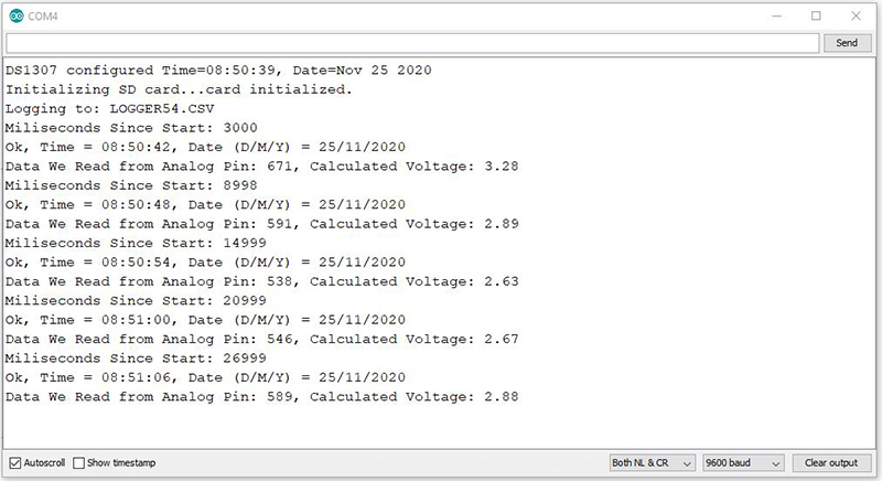
In the above code, we first activate the RTC and SD card and make a .CSV file. Next, we read the analog voltage of Arduino pin A0 and save it in the file created on the SD card. Each time, we also save the exact date and start time of the module in milliseconds in the file. Then we display the SD card data on the Serial Monitor afer each save.
The output is as follows.