
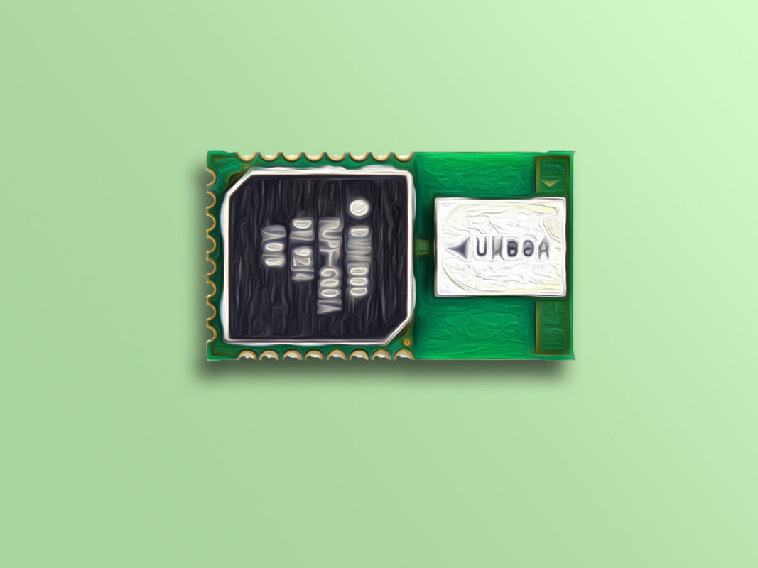
DWM1000 Transceiver Module Features
DWM1000 is an IEEE802.15.4-2011 UWB-compliant wireless transceiver module based on DecaWave’s DW1000 IC. DWM1000 measures location of objects using Real-Time Location Systems (RTLS) to a precision of 10cm indoors. This modules features a high data communication rate, up to 6.8 Mb/s, and has excellent communications range of up to 300m. It is also used in Wireless Sensor Networks (WSN).
Download the datasheet of this module here.
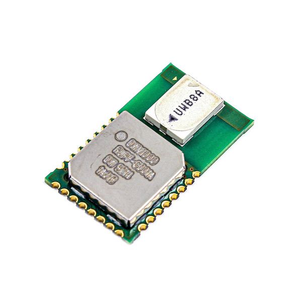
DWM1000 Positioning Module Pinout
This sensor has 24 pins:
- 3.3: Module power supply – 3.3 V
- GND: Ground
- IRQ: Interrupt from module
- SCK: SPI clock
- MOSI: Data output from master
- MISO: Data output from slave
- CS: Slave Select (often active low, output from master)
You can see pinout of this module in the image below.

Required Materials
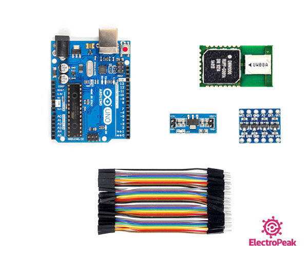
Hardware Components
Software Apps
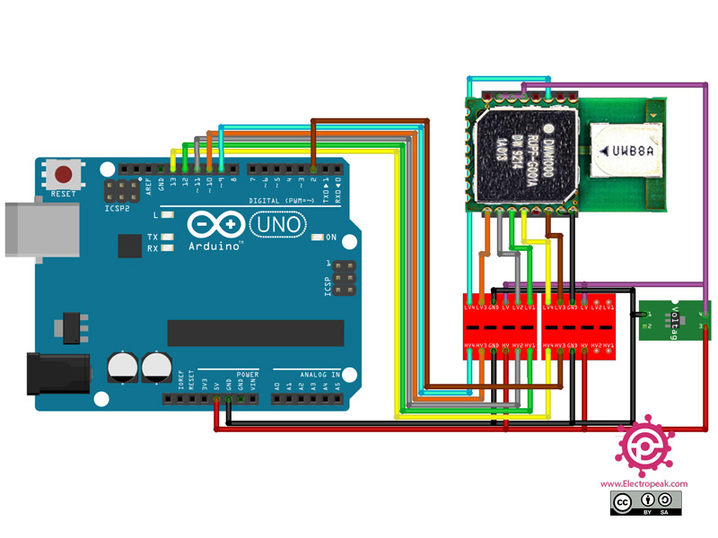
Interfacing DWM1000 with Arduino
Step 1: Circuit
The following circuit shows how you should connect Arduino to DWM1000 module. Connect wires accordingly.
Step 2: Code
Install the following library on your Arduino.
Tip
If you need more help with installing a library on Arduino, read this tutorial: How to Install an Arduino Library
Upload the following code to the first Arduino.
    /**
 *
 * @todo
 *  - move strings to flash (less RAM consumption)
 *  - fix deprecated convertation form string to char* startAsAnchor
 *  - give example description
 */
#include <SPI.h>
#include "DW1000Ranging.h"

// connection pins
const uint8_t PIN_RST = 9; // reset pin
const uint8_t PIN_IRQ = 2; // irq pin
const uint8_t PIN_SS = SS; // spi select pin

void setup() {
  Serial.begin(115200);
  delay(1000);
  //init the configuration
  DW1000Ranging.initCommunication(PIN_RST, PIN_SS, PIN_IRQ); //Reset, CS, IRQ pin
  //define the sketch as anchor. It will be great to dynamically change the type of module
  DW1000Ranging.attachNewRange(newRange);
  DW1000Ranging.attachBlinkDevice(newBlink);
  DW1000Ranging.attachInactiveDevice(inactiveDevice);
  //Enable the filter to smooth the distance
  //DW1000Ranging.useRangeFilter(true);

  //we start the module as an anchor
  DW1000Ranging.startAsAnchor("82:17:5B:D5:A9:9A:E2:9C", DW1000.MODE_LONGDATA_RANGE_ACCURACY);
}

void loop() {
  DW1000Ranging.loop();
}

void newRange() {
  Serial.print("from: "); Serial.print(DW1000Ranging.getDistantDevice()->getShortAddress(), HEX);
  Serial.print("\t Range: "); Serial.print(DW1000Ranging.getDistantDevice()->getRange()); Serial.print(" m");
  Serial.print("\t RX power: "); Serial.print(DW1000Ranging.getDistantDevice()->getRXPower()); Serial.println(" dBm");
}

void newBlink(DW1000Device* device) {
  Serial.print("blink; 1 device added ! -> ");
  Serial.print(" short:");
  Serial.println(device->getShortAddress(), HEX);
}

void inactiveDevice(DW1000Device* device) {
  Serial.print("delete inactive device: ");
  Serial.println(device->getShortAddress(), HEX);
}
Upload the following code to the second Arduino board.
    /**
 *
 * @todo
 *  - move strings to flash (less RAM consumption)
 *  - fix deprecated convertation form string to char* startAsTag
 *  - give example description
 */
#include <SPI.h>
#include "DW1000Ranging.h"

// connection pins
const uint8_t PIN_RST = 9; // reset pin
const uint8_t PIN_IRQ = 2; // irq pin
const uint8_t PIN_SS = SS; // spi select pin

void setup() {
  Serial.begin(115200);
  delay(1000);
  //init the configuration
  DW1000Ranging.initCommunication(PIN_RST, PIN_SS, PIN_IRQ); //Reset, CS, IRQ pin
  //define the sketch as anchor. It will be great to dynamically change the type of module
  DW1000Ranging.attachNewRange(newRange);
  DW1000Ranging.attachNewDevice(newDevice);
  DW1000Ranging.attachInactiveDevice(inactiveDevice);
  //Enable the filter to smooth the distance
  //DW1000Ranging.useRangeFilter(true);

  //we start the module as a tag
  DW1000Ranging.startAsTag("7D:00:22:EA:82:60:3B:9C", DW1000.MODE_LONGDATA_RANGE_ACCURACY);
}

void loop() {
  DW1000Ranging.loop();
}

void newRange() {
  Serial.print("from: "); Serial.print(DW1000Ranging.getDistantDevice()->getShortAddress(), HEX);
  Serial.print("\t Range: "); Serial.print(DW1000Ranging.getDistantDevice()->getRange()); Serial.print(" m");
  Serial.print("\t RX power: "); Serial.print(DW1000Ranging.getDistantDevice()->getRXPower()); Serial.println(" dBm");
}

void newDevice(DW1000Device* device) {
  Serial.print("ranging init; 1 device added ! -> ");
  Serial.print(" short:");
  Serial.println(device->getShortAddress(), HEX);
}

void inactiveDevice(DW1000Device* device) {
  Serial.print("delete inactive device: ");
  Serial.println(device->getShortAddress(), HEX);
}

Comments (79)
Hey there, it seems like you made a mistake in the “required parts” list. It says that you only need one Logic Level Converter, but you need 2 according to the wiring image below.
Hi…
Yes, you’re right! It has been modified now. Thanks for your attention!
Hi.. Is it possible for a tag to identify another tag???
Hi… What do you mean by tag?! Is your question regarding this tutorial?
Hey…
I’ve run this project with Arduino Leonardo instead of Uno. It works fine with 3 anchors and 1 tag but when I add the 4th anchor, it won’t range. Do you have any idea where the problem is?
Hi…
We have actually done this project with one anchor and one tag and just stopped there! So, unfortunately, I can’t say where you have gone wrong exactly. But generally speaking, these modules are so sensitive to noise, and using them with a 5V microcontroller makes it worse. So, if you use a 3.3V microcontroller like an ESP32 board and omit the logic converters from your circuit, you may get better results.
thank you
By the way, I was going to try Arduino Uno according to this page, but the suggested library for dw1000 module wont work and ends in errors while uploading the code. Is there any problem with the library?
You’re welcome!
Do you get errors while uploading the codes or compiling them? I just compiled both codes and no error popped up. If you’re just getting errors while uploading the codes, double-check the wiring. Also, make sure you have selected the right PORT.
Actually, I meant the compiling. It has got trouble with header files and stuff like these. I am pretty sure about the wiring or port selection as I have done the same project with other Arduino modules and library packages.
Yes, there might be some conflicts between the library of this tutorial and some other libraries you have. But it’s not easy to say which library of yours is causing the problem.
Hi, Mohamed. Do you mind sharing your circuit connection and how you use the code with 3 anchors + 1 tag? Thank you in advance.
Hi Danny,
the circuit remains the same as described in the article.
For the code section of 3 anchors + 1 tag, you can refer to the ‘DW1000Ranging’ library where there is an example specifically tailored for this circuit.
please to send the code for the 3 anchors and 1 tag please
Hi pablo,
you can refer to the ‘DW1000Ranging’ library where there is an example.
Hi,
I was wondering if this PCB board would work well with the DWM1000: https://www.aliexpress.com/i/4000259302044.html
Also, do we need any resistors on the outputs of the DWM1000 chip?
Thanks!
Hi,
Yes, that PCB is especially designed for DWM1000 module.
And no, you don’t need to use any extra resistors on the output of the chip. You can just use it out of the box.
Hi Mehran,
Thank you so much for the reply! So, I can simply connect the PCB board just like you showed in this tutorial, and then download the Thotro library?
Thanks again, I really appreciate it!
Actually, I was also wondering if the resistors on the PCB (here: https://www.aliexpress.com/i/4000259302044.html) would cause any problems with the Arduino Uno? The schematic is on the bottom. Should I use another Arduino board?
Thanks!
Hi,
No, that board is completely compatible with Arduino Uno. You don’t need to change your Arduino board.
You’re so welcome! Yes, you can do that without any problems.
Hi Mehran,
Thank you so much for this tutorial! I was successful in getting two sensors to provide a distance. The antenna delay has led to some errors in my measurements, but I am working to fix that. I was wondering what kind of accuracy you get? Also, readings are very easily disturbed of I touch the sensor – I wonder if that is a hardware problem, maybe due to the wires. Do you have any tips?
Hi. You’re welcome!
These modules are actually so sensitive to noise and disturbances. So, you need to make sure they are completely fixed, and they get no kind of noise. Also, use a SMD to DIP converter for them, so you can be sure that wiring is fully stable.
Hi, is it possible if I don’t use the AMS1117 3.3V DC Power Supply Module, and just connect the 3.3V of DWM1000 directly from 3.3V Arduino pin? Will it cause any issue? Thank you
Hi.
Actually, it’s not possible. The 3.3V Arduino pin doesn’t provide enough current for the DWM1000 module. So, connecting the 3.3V of DWM1000 directly to the 3.3V Arduino pin might damage your Arduino board.
I’m interested in doing this, but how will the two arduinos communicate between the two? I mean, how do you know what the other arduino to look for is to measure the distance.
Hi.
Actually, the Arduino boards are not supposed to communicate with each other. The DMW1000 modules are the ones that communicate. And here’s how they do that: As you can see, there are “startAsAnchor” and “startAsTag” command lines in each of the codes, both in line 29. That sets the module to be the anchor or the tag. The anchors keep searching for the tags around and start communicating once they find one. So, the communication is automatically done by the DWM1000 modules.
Is there a way to make it not global? That is, they communicate with each other with a key so that they are not confused if there is a tag or nearby anchors.
It occurs to me that each tag and anchor have a unique number, I print it in Arduino serial… and if the number matches then it is the one indicated, what do you recommend?
Let me explain myself better. I’m going to have several different devices that don’t connect to each other, so how do I know which one corresponds to which one? That is, 3 anchors that correspond to 1 tag and 3 more anchors that correspond to another tag. Both in the same range.
I have 3 modules for anchors on an Arduino Mega and 1 for tag on an Arduino nano.
My question is: I already know how to connect 1 tag on an arduino nano from your tutorial above, how should I connect 3 anchors on an arduino mega? I’m asking because your tutorial only shows that you use pins 9 and 2 in the code.
Well, we have done this project with only one tag and one anchor and don’t have much experience for adding more anchors. But, as you can see in one of the older comments, Mohammad is claiming to have been able to work with 3 anchors and one tag. So, you can ask him for some advice.
I put the question more clearly here with connection images: https://decaforum.decawave.com/t/x3-anchor-x1-tag-arduino/11512
Maybe you can help me.
You can find an exhaustive explanation about the DWM1000 module, its capabilities and different ways you can use it in the following links. Maybe they can help you.
https://sites.google.com/site/wayneholder/uwb-ranging-with-the-decawave-dwm1000
https://sites.google.com/site/wayneholder/uwb-ranging-with-the-decawave-dwm1000—part-ii
At the end of that manufacturer forum someone guides me with the necessary connections for 3 anchors.
Case 2: https://decaforum.decawave.com/t/x3-anchor-x1-tag-arduino/11512/13?u=principemestizo
Hi
Can I use DWM3000 instead of DWM1000 ?
Yes, it’s fully compatible with DWM1000 and you can use them interchangeably.
Hi
I used dwm3000 in the project. But I am getting error. I’ve checked the connections multiple times. There is no problem. What else could the reason be?
https://drive.google.com/file/d/1kYLlMNBO3ZTQmx-BB7F1Tpcl64bhFXPz/view?usp=sharing
Sorry, couldn’t figure out what that might be about.
Thanks very much
I’ll post here when I fix the problem.
That’s very kind of you.
DWM3000 is getting an id number, but still no communication
https://drive.google.com/file/d/1BaUrEJKst0awj43TzcmgOeHTMzBwY9iC/view?usp=sharing
https://drive.google.com/file/d/18YcEzAA7WHf1OYyRs-7_qbLwSmPGsgoU/view
It might be due to the noise that your modules are getting. Normally, they should start communicating when their return their IDs. Check the following links to see if you can figure out how to fix the problem.
https://sites.google.com/site/wayneholder/uwb-ranging-with-the-decawave-dwm1000
https://sites.google.com/site/wayneholder/uwb-ranging-with-the-decawave-dwm1000—part-ii
Monsieur,
Etant novice en arduino, j’ai suivi à la lettre votre tutoriel (qui est vraiment très bien fait) mais je n’arrive pas a récupérer les résultats, cad la distances entre l’ancre et le tag.
Pourriez vous m’éclairer s’il vous plait ?
Merci !
Adl
Hi.
First, try to write your comments in English. This way, others might be able to help you, too. And about your problem, what do you mean you don’t get the results? Do you mean you don’t see anything in the Serial Monitor? Or, you get wrong results in the Serial Monitor? In case you see nothing in the Serial Monitor, it might be because you haven’t set the Serial Monitor baud rate to the right value. Make sure you have set the baud rate to 115200.
Hello. I just bought 4 of these adapters (with soldered components): https://www.aliexpress.com/item/1005001800916186.html
What changes in relation to your diagram? Do I not need the Logic Level Converter or is it necessary? (I want to have everything ready for when they arrive)
Hi.
According to the schematics in the link, that adapter is merely an SMD to DIP converter and can help you use your DWM1000 modules more easily. So, you still need the logic level converter if you want to use the modules with a 5V logic microcontroller like Arduino Uno.
I apologize if the question is very basic, I’m new to programming with Arduino. But what is the Logic Level Converter for? I see that the line comes in from the UWB module, goes through the Logic Level Converter and then connects to the corresponding pin on the Arduino, but why? What is it for?
Hi.
Well, the Logic Level Converter has nothing to do with the programming part. As you know, the Arduino Uno is a 5V Logic board, but the DWM1000 module works with 3.3V. So, you cannot connect them to each other directly. That’s why you need to use a Logic Level Converter to interface them. It converts 5V to 3.3V, and vice versa.
I already understand, thank you very much, what it does is send 5V from the digital pins of the Arduino, MOSI, MISO, etc. to the Logic Level Converter so that it changes it from 5V to 3.3V so that it is received by the DWM1000 module (although I think the DWM1000 module is the one who sends and Arduino receives, but, it is the same logic).
What happens if I use an Arduino Nano or an Arduino Mega? I guess it’s the same, right?
Yes, Arduino Mega and Nano are also 5V logic boards, so you still need a Logic Level Converter. If you want to avoid using a Logic Level Converter, you need to use a 3.3V Logic board like Arduino Due, ESP32 or STM32 boards.
Many thanks for your advice. I am going to buy ESP32 because I see that it is more complete. What do you think of my diagram?
ESP32 Pinout: https://images-na.ssl-images-amazon.com/images/I/71TbFu6PnoL._AC_SL1001_.jpg
Diagram DWM1000 on ESP32: https://decaforum.decawave.com/uploads/default/optimized/2X/7/76bed5cee58bf1065596f5a1580f8949960f7247_2_1380x686.png
Do you see any error?
I saw that someone above recommended using an SMD to DIP. What do you think if I use this? https://www.amazon.com/-/en/KeeYees-TQFP100-adaptor-plug-heads/dp/B085L8SK7Z/
Would one of those be compatible?
Note: I plan to use an ESP32 microcontroller, so I avoid using a logic converter.
Well, none of those seem to be compatible with DWM1000 module. The one you once said you wanted to buy seemed fine. I guess that was it: https://www.aliexpress.com/item/1005001800916186.html
And also, your diagram of DWM1000 on ESP32 seems fine.
Hello friends!
In my tests, I’m only getting communication at a maximum of 4 meters. Above this distance, communication is lost.
In the documentation of the DWM1000 it says that it reaches up to 300 meters.
What am I doing wrong?
Please, can anyone help me?
Hi.
I don’t think you’re right. As far as I know, DWM1000 modules can only work within a range of 10 meters at best.
Hello can I use this guide for DWM1001 module?
Hi.
DMW1001 is a development board based on DMW1000 IC. So, they’re basically the same. But, I cannot tell whether you can use this tutorial for DMW1001 or not. It needs to be tested. You can also study the following article to see if that’s possible.
https://medium.com/garage-inside-garage/getting-started-with-ultra-wide-band-3d-positioning-dwm1000-and-dwm1001-modules-ba2f64e572b6
HELLO,
what if I want to use two DWM1000 modules for Tag purpose,
and what can I change to measure the distance between them. Like I want to measure the distance between two tags specifying some threshold value
Hi,
As you can see in the previous comments, it’s possible to use even up to 4 DMW1000 modules as tag to improve accuracy. If you want to use more than 1 DMW1000 module as tag, you can study the following links for more info.
https://sites.google.com/site/wayneholder/uwb-ranging-with-the-decawave-dwm1000
https://sites.google.com/site/wayneholder/uwb-ranging-with-the-decawave-dwm1000—part-ii
Hi,
I have a 1 tag and 1 anchor module. and i success basic sender and basic receiver code in arduino-dw1000 library, but i don’t sucess dw1000-rangring code
Please, can anyone help me?
Hi I would like to use arduino with dwm1000 for wireless vide streaming can you help me with that ? Thanks.
Hi,
I am using the setup shown in circuit above with Uno ,dwm 1000 and external power source. I am getting very inconsistent results. On the BasicConnectivityTest.ino. Most of the time the addresses(Device address and NetworkID) are read as FFFF and FFFF. Sometimes i might get the correct addresses I set like 01 and 02 but I can not replicate it reliably. I have checked all connections and voltages and they seem to be correct. Ive seen multiple forums where this is a issue I have not seen a solution yet. Do I need to switch to a different micro controller(Nano doesn’t work either).
Any help would be appreciated..
Hi, had this module accuracy about 10cm? I am going to apply this module for localization.
Hi.
According to data sheet yes is about 10cm
Hi, does the basic sender and receiver code work with this circuit diagram?
Hi dear
what do you mean about basic code?
can i use dw1000 instead dwm1000?
Hi dear
note that dw1000 is a radio chip on its own but dwm1000 is a module containing a dw1000 chip , antenna, clock and a few other parts needed to make the dw1000 hardware work.
Hi all, I am currently trying to make this work to use it to calculate the relative position of a drone to its pilot. I wanted to use two arduino nanos as anchors on the pilot and one tag on the drone itself, but I realized I would need some type of power source to power the anchors. My question now is, if anyone has measured the current draw from this circuit, whether it be with an arduino nano or anything else? This would be needed to find an appropriate battery/power bank for it, so if anyone already figured out a solution to that, feel free to post the link to it!
Hi,
u can use a simple and chip power bank for your purpose.
if I remember correctly, these two parts draw around 50-100 mA
if you want to use the li-po battery, the following product can help you Lithium Battery Power Bank Charger Module – 5V, 1A
Hi, is it possible not using logic level converter, if i use 3.3v power supply on the arduino?
Hi Oliver,
If you don’t want to use a logic level converter, you should use microcontrollers that operate with a 3.3-volt power source, such as STM, ESP, or certain Atmel modules (Arduino). Most Arduino boards operate at 5 volts and are not compatible with 3.3 volts
I am wanting to have this system placed within a moving object. As it won’t be plugged into a laptop for power, what sort of power supply would be recommeded and how would I connect it?
Hi Delbert,
For powering this module, you can use any power bank or a LiPo battery with a power bank module to maintain a stable 5-volt voltage for this purpose.
Hello Mohamed, can i use the esp32 DW1000 kit as a tag and the (Arduino+DWM1000) as anchor ?
Hello Albert,
Yes, absolutely! You can use an ESP instead of an Arduino. Additionally, with ESP32, you don’t need a logic converter—you can directly connect the ESP32 to the DW1000.
Hi, I was wondering if you knew of any documentation for connecting the DWM1000 to an ESP32 module. I am having some trouble finding the layout of connections, and understanding what additional parts are needed (for example decoupling caps, logic level shifter, etc.).
Hello,
If you are using an ESP32, you don’t need a Logic Level Converter or a 3.3V DC Power Supply Module. Everything can be connected directly to the ESP32. You can also use this code for the ESP32 by configuring the pins accordingly.
For SPI: