Contents

Interfacing TCS230 Color Recognition Sensor with Arduino

TCS230 Color Sensor Features

The TCS230 chip reads an 8×8 array of photodiodes and uses them to recognize color. Sixteen photodiodes have blue filters, 16 photodiodes have green filters, 16 photodiodes have red filters, and 16 photodiodes are clear with no filters.

The TCS230 module has 4 white LED. Photodiodes receive the light reflection of these LEDs from the surface of the object and generate an electric current depending on the color they receive.
In addition to photodiodes, this sensor also has a current to frequency converter. This converter converts current to frequency which is directly proportional to light intensity.

Note
This sensor works best in the range of 1 to 4 cm.
You can download the datasheet of this module here.

TCS230 Color Sensor Pinout

  • This module has 8 pins:
  •  VCC: Module power supply – 5V
  • GND: Ground
  • S0: Output frequency
  •  S1: Output frequency
  •  S2: Select photodiode type
  •  S3: Select photodiode type
  •  OUT: Module output

You can see the pinout of this module in the following figure.

Required Materials

Hardware Components

Arduino UNO R3 × 1
TCS230 Color Recognition Sensor × 1
male-female-jumper-wire × 1

Software Apps

Arduino IDE

Interfacing TCS230 Color Sensor with Arduino

Step 1: Circuit

Connect the module to Arduino according to the following image.

Step 2: Code

Install the following libraries on your Arduino IDE.

https://github.com/PaulStoffregen/FreqCount

https://github.com/MajicDesigns/MD_TCS230

Tip

If you need more help with installing a library on Arduino, read this tutorial: How to Install an Arduino Library

Note

The FreqCount library requires the input frequency as a digital level signal on a specific pin. For Arduino UNO you should use pin 5. If you are using other microcontroller boards, find the proper input pin from here.

Upload the following code to Arduino.
/*   
  modified on Sep 12, 2020
Modified by MohammedDamirchi from https://github.com/MajicDesigns/MD_TCS230
Home
*/ #include <MD_TCS230.h> #include <FreqCount.h> // Pin definitions #define S0_OUT 8 #define S1_OUT 9 #define S2_OUT 6 #define S3_OUT 7 #define OE_OUT 12 // LOW = ENABLED MD_TCS230 CS(S2_OUT, S3_OUT, S0_OUT, S1_OUT, OE_OUT); void setup() { Serial.begin(57600); Serial.println("[TCS230 Simple NON_BLOCKING Example]"); Serial.println("\nMove the sensor to different color to see the RGB value"); Serial.println("Note: These values are being read in without sensor calibration"); Serial.println("and are likely to be far from reality"); CS.begin(); } void readSensor() { static bool waiting; if (!waiting) { CS.read(); waiting = true; } else { if (CS.available()) { colorData rgb; CS.getRGB(&rgb); Serial.print("RGB ["); Serial.print(rgb.value[TCS230_RGB_R]); Serial.print(","); Serial.print(rgb.value[TCS230_RGB_G]); Serial.print(","); Serial.print(rgb.value[TCS230_RGB_B]); Serial.println("]"); waiting = false; } } } void loop() { readSensor(); }
After running the code, you will see the following image in the serial output.

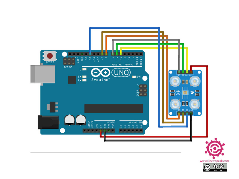
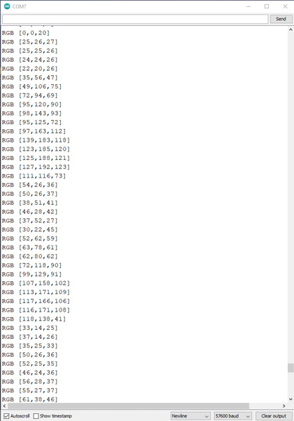
As a more complex project, let’s detect color by TCS230 sensor and show the same color on a Neopixel. You can download this sample project code here.

Liked What You See?​
Get Updates And Learn From The Best​

Leave a Reply

Your email address will not be published. Required fields are marked *