Interfacing GY-271 (HMC5883L) Compass Magnetometer with Arduino
Written by
Mohammadreza Akbari
GY-271 Compass Module Features
Magnetic current and field have directly relation with each other. When current flows in a wire (electrons start travelling in one direction), a magnetic field is created. The main idea of compass sensors is based on this relationship. The direction of the earth’s magnetic field affects the flow of electrons in the sensor. By measuring these changes in current, the sensor will be able to detect direction. The GY-271 module uses the QMC5883L chip to detect magnetic fields and its directions. The communication protocol of this module is I2C and you can connect it to different processors such as Arduino boards using two SCL and SDA pins.
You can download the QMC5883L chip datasheet here.
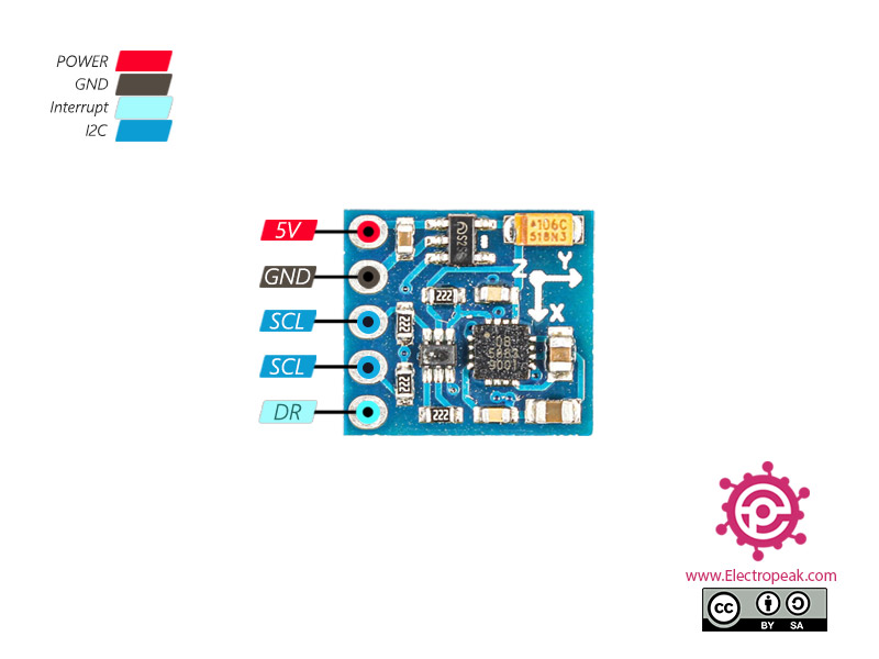
GY-271 Module has 5 pins. The application of them is as follows:
VCC: Module power supply – 3 to 5 volts
GND: Ground
SCL: I2C Clock pin
SDA: I2C Data pin
DRDY (DataReady): When the output value of the sensor is ready, an interrupt occurs in this pin. This pin is pulled up inside the module by default. When the output value of the module is ready, the pin is “0” for 250 microseconds.
You can see the pinout of this module in the followugn figure.
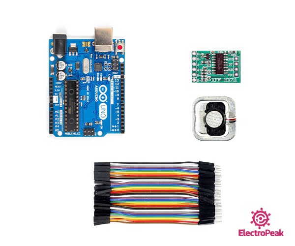
Required Materials
Hardware Components
Arduino UNO R3
×
1
GY-271 HMC5883L 3-Axis Compass
×
1
Male to Female jumper wire
×
1
Software Apps
Arduino IDE
Interfacing GY-271 (QMC5883L) Compass with Arduino
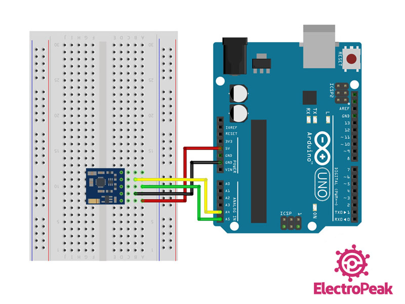
Step 1: Circuit
Connect the module to Arduino according to the following diagram
Step 2: Installing the library
Download the module library from this link and install it.
Note
If you do not know how to install a library, visit this guide.
This library has a variety of examples for interfacing a compass module. You can also use those examples.
Tip
If you have HMC5883L chip, you should use this library to interface your compass with Arduino.
Step 3: Code
After installing the library, upload the following code to your Arduino board. Then open the serial monitor to display the compass output.
/*
GY-271 Compass
modified on 02 Sep 2020
by Mohammad Reza Akbari @ Electropeak
Hi Aria,
First, ensure your wiring is correct. You can use the I2C Scanner to confirm if everything is connected properly.
Then, compare the ID obtained from the I2C Scanner with the ID specified in the library.


Comments (6)
The figure that should show the circuit does not work.
Hi Joselin,
What seems to be the issue?
missing diagram
Thank you, It’s been updated.
I’m sorry but I’ve problem. x,y,z values are all 0 .
Hi Aria,
First, ensure your wiring is correct. You can use the I2C Scanner to confirm if everything is connected properly.
Then, compare the ID obtained from the I2C Scanner with the ID specified in the library.