
Overview
What You Will Learn
- What the rotary encoder is and how it works.
- Displaying encoder position
- Controlling a LED light using a rotary encoder
- Controlling a DC motor speed and direction using a rotary encoder
What Is a Rotary Encoder?
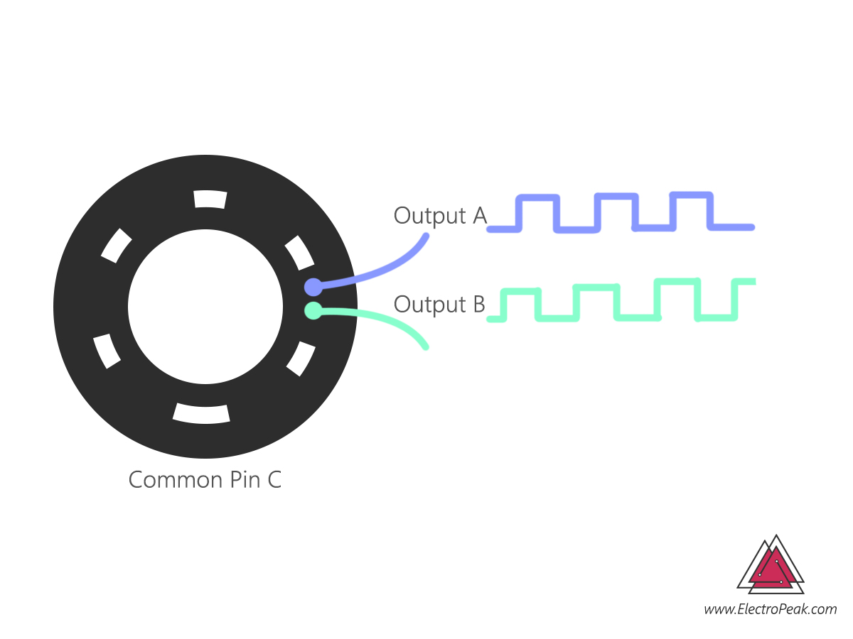
The rotary encoder is an electromechanical device that converts the position of the shaft angle to digital data. Rotary encoder has a circular plate with some holes and two channels A and B. By rotating the circular plate, when A and B channels pass the holes, a connection between that channel and a common base is established. These interruptions cause a square wave in the output channel. By counting these pulses, we can find the amount of rotation. On the other hand, channels A and B have 90 degrees of the phase difference, so you can also find the rotation direction depending on which channel pulse is ahead.
- The ability of Rotate to infinity
- 20 pulse resolution
- 5V supply voltage
How to Use a Rotary Encoder?
To use a rotary encoder, we should count the pulses of channels A and B. To do this, we used Arduino UNO and performed three projects for positioning the encoder, controlling the LED light and controlling the speed and direction of the DC motor.
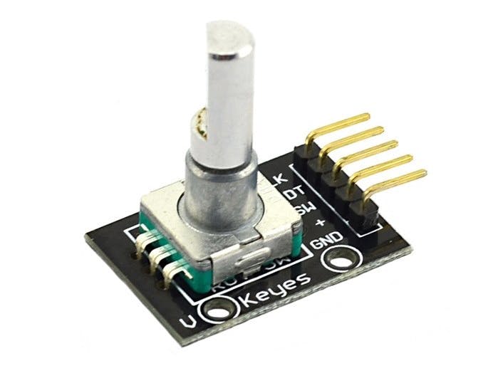
Rotary Encoder Module Pinout
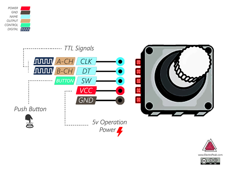
This module has 5 pins:
- CLK: Output A
- DT: Output B
- SW: Push Switch output (It is normally High, by pressing the knob, it will be LOW).
- VCC: Module power supply – 5V
- GND: Ground
You can see the pinout of this module here.
Required Materials
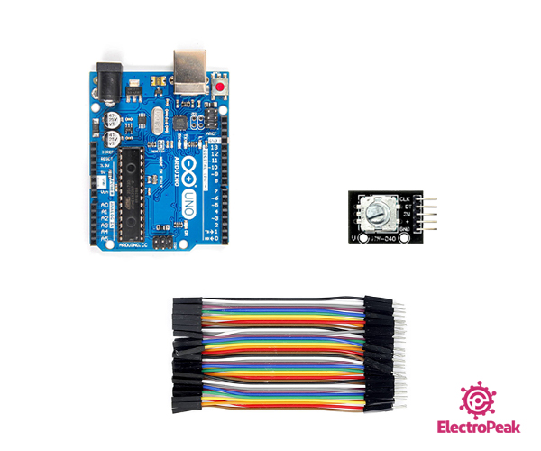
Hardware Components
Software Apps
Determining the Position of the Rotary Encoder Shaft
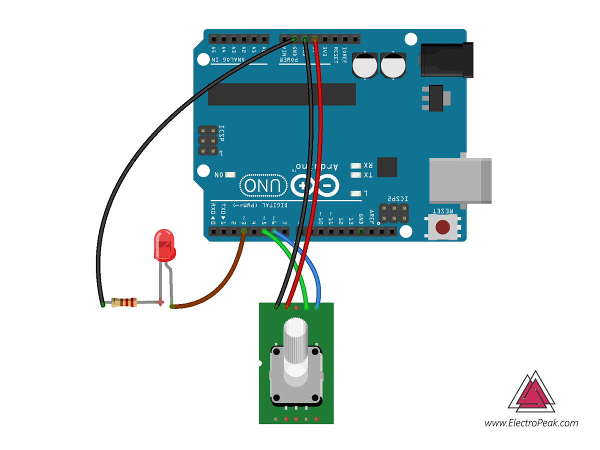
Connect the + to 5V, GND to GND pin, CLK to pin number 6, and DT to pin number 7.
You need to know the position of the shaft to use the encoder. The position of the shaft varies depending on the amount of its rotation. It changes from 0 to infinity for clockwise rotation, and from 0 to minus infinity for the counterclockwise rotation.
Upload the following code on your Arduino and see the position of the shaft encoder in the serial monitor. You can use this code for all your projects with an encoder.
/*
Rotary Encoder - get the position
modified on 23 Feb 2019
by Saeed Hosseini
Home
*/
#define encoderOutA 6 // CLK
#define encoderOutB 7 // DT
int counter = 0;
int State;
int old_State;
void setup() {
pinMode (encoderOutA, INPUT);
pinMode (encoderOutB, INPUT);
Serial.begin (9600);
//Read First Position of Channel A
old_State = digitalRead(encoderOutA);
}
void loop() {
State = digitalRead(encoderOutA);
if (State != old_State)
{
if (digitalRead(encoderOutB) != State)
{
counter ++;
}
else {
counter --;
}
Serial.print("Position: ");
Serial.println(counter);
}
old_State = State; // the first position was changed
}
To determine the encoder position, we need to connect channels A and B as inputs to Arduino. We read and save the initial value of Channel A at the beginning. Then, we read the instantaneous value of channel A, and if the value of Channel B was ahead of it, we decrease the counter. Otherwise, we increase the counter number.
Controlling a LED Light with Shaft Rotation
Circuit
Code
/*
Rotary Encoder - LED Brightness Control
modified on 23 Feb 2019
by Saeed Hosseini
Home
*/
#define encoderOutA 6 // CLK
#define encoderOutB 7 // DT
#define LED 9 // LED , must connect to pwm pin
int brightness = 0;
int State;
int old_State;
void setup() {
pinMode (encoderOutA, INPUT);
pinMode (encoderOutB, INPUT);
pinMode (LED, INPUT);
Serial.begin (9600);
//Read First Position of Channel A
old_State = digitalRead(encoderOutA);
}
void loop() {
State = digitalRead(encoderOutA);
if (State != old_State)
{
if (digitalRead(encoderOutB) != State)
{
brightness ++;
}
else {
brightness --;
}
if (brightness >= 255) brightness = 255;
if (brightness <= 0) brightness = 0;
Serial.print("brightness: ");
Serial.println(brightness);
}
old_State = State; // the first position was changed
analogWrite(LED , brightness);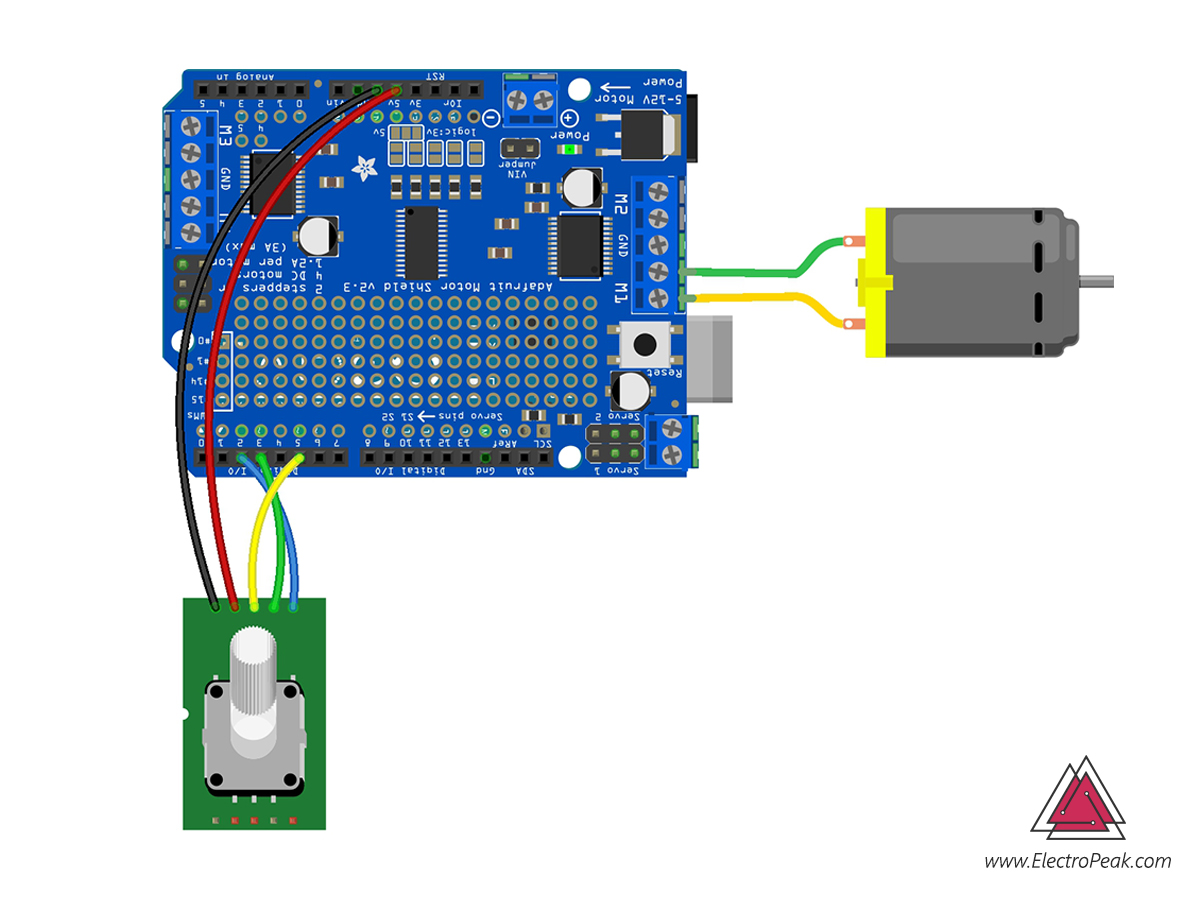
}Controlling DC Motor Speed and Direction with Interrupt
Circuit
Code
First, install the Adafruit_Motor_Shield_library on your Arduino IDE.
Then, upload the following code on your Arduino Board.
/*
  Rotary Encoder - Controlling a DC Motor using L293D Shield
  modified on 23 Feb 2019
  by Saeed Hosseini
  Home
*/

#include <AFMotor.h>

#define CLK 2
#define DT  5
#define SW  3

AF_DCMotor motor(1, MOTOR12_64KHZ);

int motor_dir = 0;
int State;
int old_State, change;
volatile int motor_speed = 0;
volatile boolean buttonState = false;

void setup() {
  Serial.begin(9600);
  pinMode(CLK, INPUT);
  pinMode(DT, INPUT);
  pinMode(SW, INPUT_PULLUP);
  old_State = digitalRead(CLK);
  attachInterrupt (digitalPinToInterrupt(CLK), encoder_detect, CHANGE);
  attachInterrupt (digitalPinToInterrupt(SW), button_detect, FALLING);
}
void loop() {
  if (!buttonState)
  {
    if (motor_speed > 0)
    {
      motor.setSpeed(motor_speed);
      motor.run(FORWARD);
      Serial.print("Move Forward: ");
      Serial.println(motor_speed);
    }
    else if (motor_speed < 0)
    {
      motor.setSpeed((motor_speed) * (-1));
      motor.run(BACKWARD);
      Serial.print("Move Backward: ");
      Serial.println(motor_speed);
    }
  }
  if (buttonState == true || motor_speed == 0)
  {
    motor.run(RELEASE);
    Serial.println("Break");
  }
}

void encoder_detect ()  {
  buttonState = false;
  State = digitalRead(CLK);
  if (State != old_State)
  {
    if (digitalRead(DT) != State)
    {
      motor_speed ++;
      if (motor_speed >= 255) motor_speed = 255;
    }
    else {
      motor_speed --;
      if (motor_speed <= -255) motor_speed = -255;
    }
  }
  old_State = State;
}

void button_detect()
{
  buttonState = true;
}
In this code, we have used an interrupt to read the shaft and key position. For more information about interrupts, you can check the Arduino Website.
The motor breaks by pushing the encoder key or setting the encoder in position 0.
You can see how to drive DC motor with the L293D shield here.

Comments (6)
great mate i appreciate your help to finish school project.cheers!
Thats great, we always try to do our best
i am not able to make this it shows’ expected unqualified id before numeric constant’
Which line exactly do you get the error from?
I got this web site from my pal who informed
me regarding this web page and now this time I am visiting this web site and reading very informative articles or reviews
at this place.
Hi my friend.
We are so happy to hear this. If you ever come up with any question, you’re so welcome to ask.