
Overview
What you will learn
- You will learn how to generate a specific QR code.
- You will learn how to make a log in page by ESP8266.
- You will be able to unlock a door via your cell phone.
Secure Doors by Smart Lock
These days, You can improve your home or office security by adding technology. Using smartphones and devices become very popular for people and it’s a good option for us to make our stuffs smarter. Every day, Engineers and technicians produce new systems and tools that you can make smarter home automation by using them and create new ways to make your life safer and easier. Probably you have seen smart locks for doors that have a keypad or use a fingerprint to set the door lock or unlock.

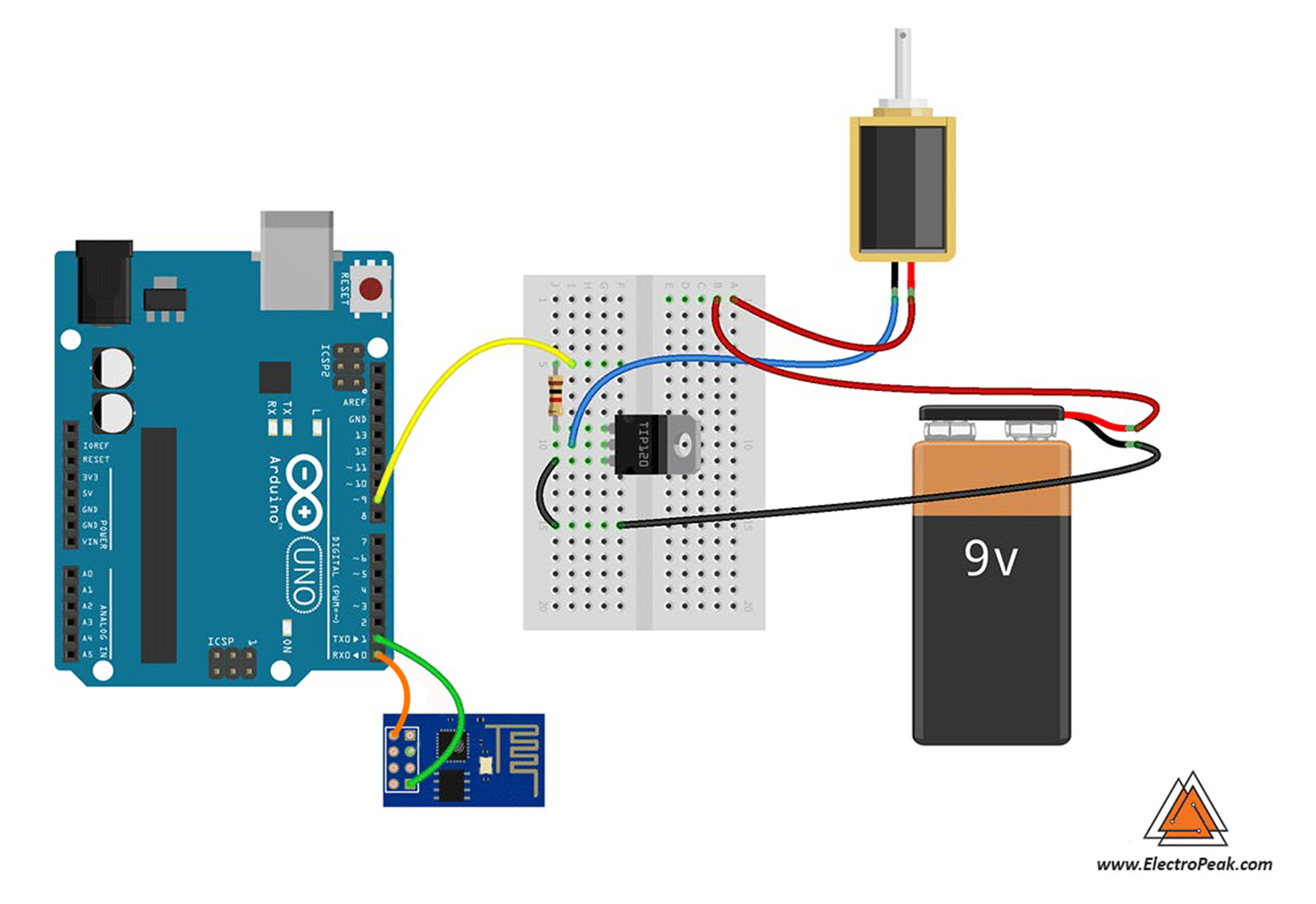
In this project, We want to make an Arduino based system that helps you to make a login section for a door by wifi and solenoid lock. We don’t use keypad or complicated mechanical elements and these are benefits of this system. We only stick a QR code on the door and the allowed people can scan it to see the login page and enter their password. After typing the password, the solenoid lock will be activated. We only use an Arduino board and a driver for the solenoid and an ESP8266 to make a connection to local wifi. Let’s do it.
Required Materials
Hardware Components
Software Apps
Circuit
Code
First we write a code for ESP-01 to make a log-in page and receive password from user then send it to Arduino by the Serial port. Then we write another code for Arduino to get data from ESP-01 and control the servo motor. You can use Arduino IDE to compile both codes and Upload them to boards.
You must add the library and then upload the code. If it is the first time you run an Arduino board, don’t worry. Just follow these steps:
- Go to www.arduino.cc/en/Main/Software and download the software of your OS. Install the IDE software as instructed.
- Run the Arduino IDE and clear the text editor and copy the following code in the text editor.
- Choose the board in tools and boards, select your Arduino Board.
- Connect the Arduino to your PC and set the COM port in tools and port.
- Press the Upload (Arrow sign) button.
- You are all set!
String inputString = "";         // a String to hold incoming data
bool stringComplete = false;  // whether the string is complete

void setup() {
  // initialize serial:
  Serial.begin(115200);
  // reserve 200 bytes for the inputString:
  inputString.reserve(200);

  pinMode(9,OUTPUT);
}

void loop() {
  // print the string when a newline arrives:
  if (stringComplete) {
    if (inputString=="your_password")
   {
       digitalWrite(9,HIGH);
       delay(300);
       digitalWrite(9,LOW);

       Serial.println(inputString);
       // clear the string:
       inputString = "";
      stringComplete = false;
    }
  }
}


void serialEvent() {
  while (Serial.available()) {
    // get the new byte:
    char inChar = (char)Serial.read();
    // add it to the inputString:
    inputString += inChar;
    // if the incoming character is a newline, set a flag so the main loop can
    // do something about it:
    if (inChar == '\n') {
      stringComplete = true;
    }
  }
}
Now its time to upload the ESP-01 code. You should use the Arduino IDE to upload the sketch to ESP. Before uploading the code, you should select ESP board for IDE.
Go to File>Preferences and add http://arduino.esp8266.com/stable/package_esp8266com_index.json in the additional boards. Then download and install it. Now you can see the ESP boards in Tools>Board. Select “Generic ESP8266 Module” and copy the code in a new sketch. Then you should set USB to TTL Converter as Uploader hardware. Just plug the converter in and set the right port in Tools>Port. It’s ready to Upload.
#include <ESP8266WiFi.h>
#include <ESP8266WebServer.h>
// WiFi network
const char* ssid = "YourSSID";
const char* password = "YourPASSWORD";
ESP8266WebServer server ( 80 );
char htmlResponse[3000];
void handleRoot() {
snprintf ( htmlResponse, 3000,
"<!DOCTYPE html>\
<html lang=\"en\">\
<head>\
<style>\
body {background-color: rgb(160, 0, 53);}\
h3 {color: white;text-align:center;}\
p {color: white; text-align:center;}\
div {color: white; text-align:center;}\
ID {text-align:center;}\
input {text-align:center;}\
</style>\
<meta charset=\"utf-8\">\
<meta name=\"viewport\" content=\"width=device-width, initial-scale=1\">\
</head>\
<body>\
<h3>\<canter>Electropeak Smart Security Door</canter>\</h3>\
<p>\<canter>Please type your ID</canter>\</p>\
<div>ID: <input type='text' name='pass_word' id='pass_word' align='center' size=10 autofocus></div> \
<div>\
<br><button id=\"save_button\">Log In</button>\
</div>\
<script src=\"https://ajax.googleapis.com/ajax/libs/jquery/1.11.3/jquery.min.js\"></script>\
<script>\
var pass;\
$('#save_button').click(function(e){\
e.preventDefault();\
pass = $('#pass_word').val();\
$.get('/save?pass=' + pass, function(data){\
console.log(data);\
});\
});\
</script>\
</body>\
</html>");
server.send ( 200, "text/html", htmlResponse );
}
void handleSave() {
if (server.arg("pass")!= ""){
Serial.println(server.arg("pass"));
}
}
void setup() {
// Start serial
Serial.begin(115200);
delay(10);
// Connecting to a WiFi network
Serial.println();
Serial.println();
Serial.print("Connecting to ");
Serial.println(ssid);
WiFi.begin(ssid, password);
while (WiFi.status() != WL_CONNECTED) {
delay(500);
Serial.print(".");
}
Serial.println("");
Serial.println("WiFi connected");
Serial.println("IP address: ");
Serial.println(WiFi.localIP());
server.on ( "/", handleRoot );
server.on ("/save", handleSave);
server.begin();
Serial.println ( "HTTP server started" );
}
void loop() {
server.handleClient();
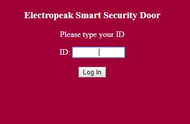
}After uploading the code, Open Serial monitor of Arduino IDE and get your IP. Now if you type the IP in a browser URL bar, You can see UI of the web server. Type your ID in the text box and if you do it correctly, Arduino will activate the lock. Notice that you have to connect to a common wifi router with ESP8266.
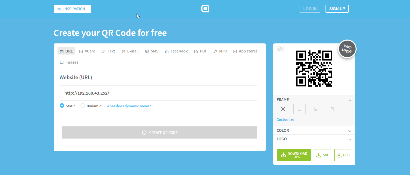
Now it’s time to make a QR code and make a simple way for users to reach this webpage. There are a lot of online tools to generate a specific QR code for you. We suggest this one.
Just copy your IP in the bar and click on “Create QR Code”.

What’s Next?
Here are a few suggestions:
- Try to make a professional UI for the login page.
- Try to add more options for users such as different permission levels or time-based permission.

Comments (51)
Hello there, thank you for the great explanation.
I have 1 question; once we have successfully unlocked the door, does the door will be locked automatically once it is closed?
Thank you.
Hi, yes it does.
hello im interesting to modify your work using wifi with material using wifi relay module and controlled the program using smart phone what should i do?
Hi there, I’m a student from Indonesia. I’m interesting to modify your project.
In my modification, I want to use NodeMCU ESP8266 only. And without barcode.
So solenoid is controled by apps in smartphone if only connect to internet wherever it is, without password.
It’s like on/off LED. So it’s just simple than yours. But I don’t know how to set the schematic on NodeMCU ESP 8266.
So i’m very glad if you can help me.
Hi
just connect the solenoid to one of the NodeMCU GPIO(for example D2).
That’s it.
but i use NodeMCU ESP8266 not ESP-1 like yours? is it working the same?
And how to connect it to the app?
Yes, it is.
Do you use the Blynk app?
Hello there I really like this project and it will really fit my needs perfectly.
However i am not able to replicate it fully …. i got your code uploaded into the Arduino Uno R3 … in the field where we have to enter our individual password i did that (as a matter of fact i tried it all letters only and than numbers only or a combination because of the inputString variable)
I got the code uploaded on the ESP-01 ….i entered the log in and the password for my wifi ….the ESP signs right on onto my network and i am able to access the webpage just fine where we enter the password. However after entering the password and clicking Log In there is no relay clicking!!!
I have connected a simple 5v relay to pin 9 of the Arduino and connected the Tx of the Uno to Rx of the ESP and the Tx of the ESP to Rx of the Uno ( i do not understand why you have the GPIO2 of the ESP connected to the Rx of the Arduino on your little pic/ wiring diagram i tried that also to no avail…is that just a drawing mistake??).
All… the little 5v relay, the ESP and the Uno itself are powered from a single 12v source through the Uno (you have forgotten to mention on the write up that the CHPD pin of the ESP has to be connected to the 3v3 line also for the ESP to boot correctly if you are using Dupont jumper wires as the majority of us are)
On the Arduino sketch you say Serial.begin 9600 while on the ESP sketch you say Serial.begin 115200 …. aren’t they supposed to be the same so the 2 boards can communicate on the same baud rate?? (i tried both by the way and still it does not work)
Isn’t there supposed to be a Serial.write statement on the ESP sketch ?? (i am sorry i am no Arduino expert i just have seen this before on other sketches)
Can i please have a copy of your own configuration it will really mean a lot to me if i can get this to work in my home automation setup because we have a lot of friends and family that come and go in our house. please write me directly at…. grabocka (at) sbcglobal.net
thank you in advance
Denis
ps I have tried 2 differnt Arduino Uno’s 2 different ESP-01 and 2 different relays still no success
Hi
Thanks for your comment, we updated this tutorial. please check it again
Hey Saeed,
Thank you for your prompt reply ….it shows that you care and i really appreciate that.
However it still does not work i see that you have corrected the diagram for the tx/rx connections and changed the baud rate on both boards to 115200.
Again the Esp connect to my network i am able to put in the password however that argument does not seem to be transmitted to the Arduino Uno
I know i have the connections right and i have uploaded the appropriate sketches with the appropriate changes but it is not working!
What am i doing wrong??
Is this the right order of things ( and i am sorry i may be tottally off i am not an expert so forgive me please) but it seems like we are passing the argument without starting the serial port!!! or am i wrong
void handleSave() {
if (server.arg(“pass”)!= “”){
Serial.println(server.arg(“pass”));
}
}
void setup() {
// Start serial
Serial.begin(115200);
delay(10);
// Connecting to a WiFi network
Serial.println();
Serial.println();
Serial.print(“Connecting to “);
Serial.println(ssid);
WiFi.begin(ssid, password);
while (WiFi.status() != WL_CONNECTED) {
delay(500);
Serial.print(“.”);
}
Serial.println(“”);
Serial.println(“WiFi connected”);
Serial.println(“IP address: “);
Serial.println(WiFi.localIP());
server.on ( “/”, handleRoot );
server.on (“/save”, handleSave);
server.begin();
Serial.println ( “HTTP server started” );
Please help me solve this
Again thank you
Denis
Hi Denis,I’m sorry for delay in answering . I checked all parts of code and run whole project again. The code is correct and I can get password in Arduino serial terminal.
I have some suggestions for you. ESP-01 module has a very weak circuit and sometimes its hard to making run without problem. Voltage and current of this module are very important and make sure your wires are thick enough to give needed ampere to module. If you can’t replace wires, try to connect it to a higher voltage power supply like 4 volt. Another way is replacing ESP-01 with a higher version of ESP modules like NodeMCU and try this code on that. I guess your main problem is ESP and for debugging step by step, Only test the ESP and see result in serial monitor without arduino as Step 1.
Any new word on this??? Please read the above comment although i did the above changes and changed the baud rate to 115200 on both boards there is still no communication.
The ESP-01 web-server works fine but it does not seem to send any data to the Arduino UNO or Ardunio Uno is not processing anything.
There has got to be something wrong with the sketch codes cause there is nothing wrong with the hardware and the connections please confirm that the sketch works just he way it is on your end (obviously with your passwords etc)
I really want to get this to work
Any help to troubleshoot will be greatly appreciated
thank you in advance
Denis
Hi again.
in ESP code use Serial.print(password) instead of Serial.println(password), or in Arduino code add “\n” after the password (password\n)
hi there and thank you for replying
which line is the one you are referring to on the ESP code??
I do not see any Serial.println(password)
Thank you again
Denis
Dear Denis
Check line 48. Change ” Serial.println(server.arg(“pass”));” to ” Serial.print(server.arg(“pass”));”
Kind regards
When i compile the code for the ESP without changing anything just as you have posted i get the following errors.
:\Users\Denis Grabocka\Documents\Arduino\Sketches\esp01DoorLock\esp01DoorLock.ino:31:95: warning: backslash and newline separated by space [enabled by default]
\
^
C:\Users\Denis Grabocka\Documents\Arduino\Sketches\esp01DoorLock\esp01DoorLock.ino:36:37: warning: backslash and newline separated by space [enabled by default]
pass = $(‘#pass_word’).val();\
^
C:\Users\Denis Grabocka\Documents\Arduino\Sketches\esp01DoorLock\esp01DoorLock.ino:40:9: warning: backslash and newline separated by space [enabled by default]
});\
^
C:\Users\Denis Grabocka\Documents\Arduino\Sketches\esp01DoorLock\esp01DoorLock.ino: In function ‘void handleRoot()’:
C:\Users\Denis Grabocka\Documents\Arduino\Sketches\esp01DoorLock\esp01DoorLock.ino:10:1: warning: unknown escape sequence: ‘<' [enabled by default]
"\
^
C:\Users\Denis Grabocka\Documents\Arduino\Sketches\esp01DoorLock\esp01DoorLock.ino:10:1: warning: unknown escape sequence: ‘<' [enabled by default]
C:\Users\Denis Grabocka\Documents\Arduino\Sketches\esp01DoorLock\esp01DoorLock.ino:10:1: warning: unknown escape sequence: '<' [enabled by default]
C:\Users\Denis Grabocka\Documents\Arduino\Sketches\esp01DoorLock\esp01DoorLock.ino:10:1: warning: unknown escape sequence: '<' [enabled by default]`
Do they affect the behavior of the communication or not really
Again i am sorry i do not know much about coding i jam good at following along but i am willing to learn and i greatly appreciate your help
Denis
It is still not working
I can hear the relay clicking now during boot up as soon as i plug it in but not though entering the correct password (before there was absolutely nothing)
Is there a way we can get this to work without the Arduino Uno just the ESP board ….maybe i can put it in a NodeMCU and a relay
Denis
Yes, you can use Nodemcu or Wemos D1 and remove Arduino UNO. Nodemcu has enough GPIO pins for this project.
Hey , I’m doing this project but when i put the password on html, it doesn’t send the command for digital write, how is the connection for esp8266 because im wiring vcc gnd tx rx and ch-pd is it correct?
i’ve put a led instead of the motor , just to test it , so when the password is correct the led will turn on , but it’s not working
Hi.
First of all, you need to program ESP32. Check the following link to see how to do that. https://create.arduino.cc/projecthub/pratikdesai/how-to-program-esp8266-esp-01-module-with-arduino-uno-598166
After that, you can program the Arduino Uno and use the schematics given in the article to get the right results.
Thanks very nice blog!
So glad you enjoyed it.
thanks for your work , this really helpful for me , but I have a question , how can we set USB to TTL Converter as Uploader hardware because I don’t understand this part
You’re welcome!
Well, as you can see, the ESP-01 board has 8 pins and no miniUSB or microUSB port. So, you can’t just connect it to a PC and program it. To do that, you need to use a USB to TTL converter. For example, this converter can be helpful: “https://electropeak.com/usb-ttl-pl2303”
Also, you can check the following link to see how you can connect the USB to TTL converter to the ESP-01: “https://behind-the-scenes.net/connecting-the-esp8266-to-a-breadboard-and-ftdi-programmer/”
this is really helpful thank you , can I use this USB to TTL converter with ESP8266 ?
Yes, it’s pretty much straight-forward. The link I recommended at the end of my previous comment fully explains how you can do that. Also, this link can be so helpful: “https://www.diyhobi.com/flash-program-esp-01-using-usb-serial-adapter/”
hello i have an idea what if this project can record everyone who scanned and open the door and it will tell the time and date when their unlock the door? i think it would be great!
Hi.
Yes, that’s a great feature to add to this project. For that, you also need to add an RTC module to the circuit. The best RTC modules you can use are DS3231, DS1307 and DS1302. You can use the following tutorials to see how you can interface any of those RTC modules with Arduino:
https://electropeak.com/learn/interfacing-ds3231-real-time-clock-rtc-module-with-arduino/
https://electropeak.com/learn/interfacing-ds1302-real-time-clock-rtc-module-with-arduino/
https://electropeak.com/learn/interfacing-ds1307-i2c-rtc-real-time-clock-module-with-arduino/
wow thank you kind sir!
You’re so welcome!
hello, I can’t get the IP address for the esp01. I have tried every solution on the internet but to no avail. can you help me with this?
Hi,
Are you sure you have selected the right Baud rate for your Serial Monitor? What exactly do you get in the Serial Monitor?
i get ……….. in the serial monitor
I use 115200 baud rate
Well, make sure you have opened the serial monitor of the right PORT. You need to open the serial monitor of ESP32 to get the local IP.
yes it works thank you. but i cant enter the ID now for some reason what do you think?
So, you mean you can’t get the IP in the Serial Monitor? Or you get it but nothing happens when you type in the browser?
i finally get the ip address but now I’m stuck on entering the ID to unlock the lock. when I try to enter the ID or password nothing happens
Well, it’s weird. You’ve already passed the complicated steps. Do you have a multimeter? You may need it to troubleshoot the issue. First, you need to make sure that the Arduino is performing well. Use a multimeter to measure the voltage of digital pin 9 of the Arduino board when you enter your ID and password. If it becomes HIGH when you enter your info, there is nothing wrong with the microcontrollers, and they’re both properly programmed. Then, the problem might be related to the transistor or resistor in your circuit.
i am unable to convert usb to ttl and unable to dumb the code in esp8266
can anyone help me
Hi.
Could you explain your problem more exactly? What do you mean you can’t convert USB and TTL? And are there any errors you get when you upload the code to your ESP8266 board?
Hi,
Can i know the connection of circuit before uploading the code? It is same as shown in the picture or the picture is the final result?
Hi.
The connection of the circuit is the same as shown in the picture.
Hi, Nice project thank you! Can you please show how to change the password, because I cant find where to change the password and how to change the password in the code, can you please guide me.
Hi.
Thank you for your kindness and also your good opinion.
in top of header in c code you can find :
const char* ssid = “YourSSID”;
const char* password = “YourPASSWORD”;
as you see you can set any password instead of YourPASSWORD
hello, i have an error when uploading second coding which is lead to error: espcomm_upload_mem failed
error: espcomm_upload_mem failed. how to fix this error
Hi.
dear please be sure that you choose right board from Tools in Arduino IDE
and try it with deferent Upload Speed.
it should be work.
my lock solenoid not open or close,please help
Hi.
whats your exact problem?
I mean did you check your voltage supply?
could you please connect solenoid to DC Voltage Directly?
can we add rfid with it ? so that it will be two way verification type
please reply….
Hi.
yes you can use RFID reader without problem.
just note that it need Seloniod with support RFID reader.