Contents

Instagram Likes Speedometer by Arduino & ESP8266

Overview

It would fun to see how your Instagram posts perform in action! We are going to build a gauge that shows your Likes per minute speed. In this article, you will learn how to get data from web pages by ESP8266 and send them to Arduino to analyze and run other actuators. 

What You Will Learn

An Introduction to ESP8266

Wireless interfacing, connecting to the web and remote controlling are features that can be very helpful in many projects. ESP-8266 is a low-cost microchip with full TCP/IP (Transmission Control Protocol and Internet Protocol), 32-bit MCU, 10-bit ADC and different interfaces like PWM, HSPI and I2C that enables microcontrollers to connect to the Wi-Fi networks. It is one of the best solutions for adding wifi to projects and (but not the only one.)

This microchip comes with different types of module like ESP-01, ESP-12 or other development boards and breakouts like NodeMCU devkit, Wemos and Adafruit Huzzah. The difference is their pins, components needed for easier usage and also price. The microchip has 32 pins that 16 pins of it are GPIO; depending on the model, the number of GPIOs provided is different. For ESP-01 it is just two pins but other models like breakouts have all of them. When using ESP-8266, you will need a serial interface to communicate and program. Simple modules usually don’t have serial converter (FTDI is usually suggested but other converters can be used, too) and it should be provided separately. Regulators, built-in LEDs, and pull-up or down resistors are other features that some models may have; the lowest cost between all of these modules is for ESP-01 and it’s our choice now.

ESP-01 is the first module that comes for esp-8266 and it has just two GPIO pin and needs 3.3V for power. It doesn’t have a regulator, so make sure to have a reliable power supply. It doesn’t have a converter, therefore you need USB to TTL convertor. Converter for this module (and also other models of ESP) should be in 3.3V mode. The reason for this is the convertor will make 0 and 1 via pulses, and voltage of these pulses should be recognizable for ESP, so check this before buying.  Because of the limited quantity GPIO pins and also their low current (12mA per each one), we may need more pins or more current; so we can easily use Arduino with a module to access its IO pins (another way to access more GPIO pins is wiring out a very thin wire on the chip to the pin headers you need, but its not a good and safe solution). If you don’t want to use another board, you can design or use a circuit to increase current.

In this project, We want to connect ESP-01 to the Internet and get some data from Instagram pages. Then we send the data to Arduino and after processing it, Arduino changes the location of Servo pointer according to data. Let’s do it.

Required Materials

Hardware Components

ESP8266 WiFi Module with PCB Antenna × 1
Arduino Nano × 1
FTDI USB to TTL Converter × 1
TowerPro MG995 55G Metal Gear Servo × 1

Software Apps

Arduino IDE

Circuit

Code

First we write a code for ESP-01 to get data from Instagram pages and send them to Arduino by the Serial port. Then we write another code for Arduino to get data from ESP-01 and control the servo motor. You can use Arduino IDE to compile both codes and Upload them to boards.

You must add the library and then upload the code. If it is the first time you run an Arduino board, don’t worry. Just follow these steps:

  1. Go to www.arduino.cc/en/Main/Software and download the software of your OS. Install the IDE software as instructed.
  2. Run the Arduino IDE and clear the text editor and copy the following code in the text editor.
  3. Choose the board in tools and boards, select your Arduino Board.
  4. Connect the Arduino to your PC and set the COM port in tools and port.
  5. Press the Upload (Arrow sign) button.
  6. You are all set!
#include "Servo.h"
Servo myservo;

String inputString = "";         // a String to hold incoming data
boolean stringComplete = false;  // whether the string is complete

long flike;
long like;
long mlike;

void setup() {
  // initialize serial:
  Serial.begin(115200);
  myservo.attach(9);
  // reserve 200 bytes for the inputString:
  inputString.reserve(200);
}


void loop() {
  // print the string when a newline arrives:
  
  if (stringComplete) {
    flike=like; 
    like=inputString.toInt();
    Serial.println(like);
    // clear the string:
    inputString = "";
    stringComplete = false;
  }

  mlike=like-flike;
  mlike=mlike*20;
//Serial.print(mlike);
  if (mlike==0) {mlike = 0;}
  if (mlike==1) mlike = 20;
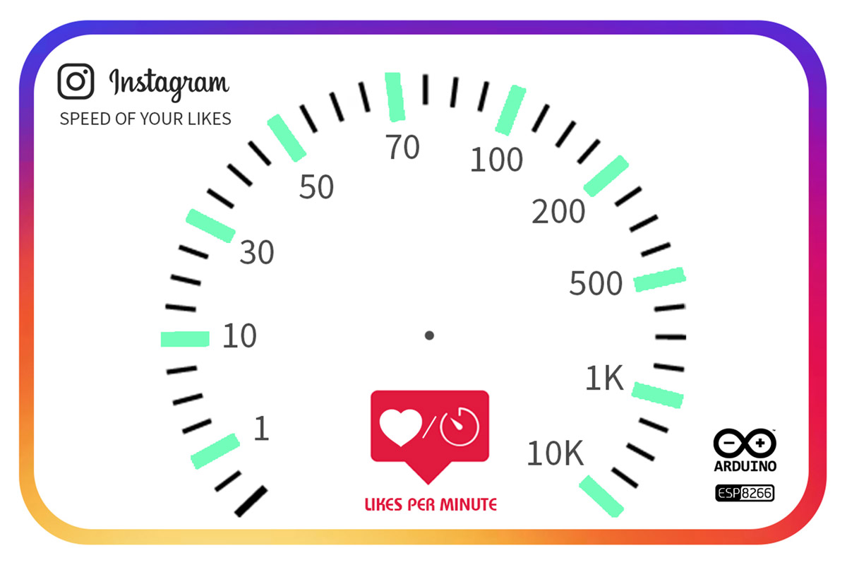
  if (mlike<=10 && mlike>1) mlike = map(mlike, 1, 10, 20, 50);
  if (mlike<=30 && mlike>10) mlike = map(mlike, 10, 30, 50, 70);
  if (mlike<=50 && mlike>30) mlike = map(mlike, 30, 50, 70, 90);
  if (mlike<=70 && mlike>50) mlike = map(mlike, 50, 70, 90, 110);
  if (mlike<=100 && mlike>70) mlike = map(mlike, 70, 100, 110, 130);
  if (mlike<=200 && mlike>100) mlike = map(mlike, 100, 200, 130, 150);
  if (mlike<=500 && mlike>200) mlike = map(mlike, 200, 500, 150, 170);
  if (mlike<=1000 && mlike>500) mlike = map(mlike, 500, 1000, 170, 180);
  myservo.write(mlike);
  //Serial.print("    ");
  //Serial.println(mlike);
   delay(15);     
  
}

/*
  SerialEvent occurs whenever a new data comes in the hardware serial RX. This
  routine is run between each time loop() runs, so using delay inside loop can
  delay response. Multiple bytes of data may be available.
*/
void serialEvent() {
  while (Serial.available()) {
    // get the new byte:
    char inChar = (char)Serial.read();
    // add it to the inputString:
    inputString += inChar;
    // if the incoming character is a newline, set a flag so the main loop can
    // do something about it:
    if (inChar == '\n') {
      stringComplete = true;
    }
  }
}

Now its time to upload the ESP-01 code. We want to use Arduino IDE to upload the sketch to ESP. Before uploading the code, you should select ESP board for IDE.

Go to File>Preferences and put http://arduino.esp8266.com/stable/package_esp8266com_index.json in the additional boards. Then download and install it. Now you can see the ESP boards in Tools>Board . Select “Generic ESP8266 Module” and copy the code in a new sketch. Download the “InstagramStats” library and add it to IDE. Note that we have modified the library, So you should download it here. Then you should set USB to TTL Converter as Uploader hardware. Just plug the converter in and set the right port in Tools>Port. It’s ready to Upload.

Necessary Files and Downloads:

 json-streaming-parser-master

&

#include "InstagramStats.h"
#include "ESP8266WiFi.h"
#include "WiFiClientSecure.h"
#include "JsonStreamingParser.h"

char ssid[] = "Electropeak.com";       // your network SSID (name)
char password[] = "electropeak1928374650";  // your network key

WiFiClientSecure client;
InstagramStats instaStats(client);

unsigned long delayBetweenChecks = 1000; //mean time between api requests
unsigned long whenDueToCheck = 0;

//Inputs
String userName = "arduino.cc"; // Replace your Username


void setup() {

  Serial.begin(115200);
  
  WiFi.mode(WIFI_STA);
  WiFi.disconnect();
  delay(100);

  WiFi.begin(ssid, password);
  while (WiFi.status() != WL_CONNECTED) {
    delay(500);
  }
  IPAddress ip = WiFi.localIP();
}

void getInstagramStatsForUser() {
  InstagramUserStats response = instaStats.getUserStats(userName);
  Serial.println(response.followedByCount);
}

void loop() {
  unsigned long timeNow = millis();
  if ((timeNow > whenDueToCheck))  {
    getInstagramStatsForUser();
    whenDueToCheck = timeNow + delayBetweenChecks;
  }
}

Assembling

Upload the code and wire up the circuit according to the picture. Now it’s time to make a frame for this circuit. we used a laser cutting machine to make a frame with plexiglass and designed a gauge sketch to stick on it. We have also made a pointer for the gauge with paper.

What’s Next?

You can improve this project as you wish. Here are a few suggestions:
  • Change the InstagramStats library to receive other data such as the number of followers and so on.
  • Change the speed of getting data to decrease your internet utilization.
  • Try to get the data from videos posts on Instagram.
Liked What You See?​
Get Updates And Learn From The Best​

Comments (4)

  • Karen Reply

    Hello,
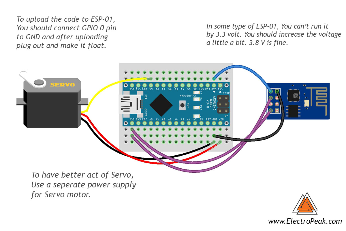
    I am trying to follow the steps, and may I ask if there would be a more detailed instruction on “setting USB to TTL converter as uploader hardware”, and the circuit board for plugging in the FTDI USB to TTL Converter please?

    Cheers!

    July 30, 2019 at 4:21 am
  • Hekmat Reply

    Hello
    Please make a video education from ps2 radiocontrol & Explanation .
    Please give me video .
    I love arduino board ptoject .

    January 6, 2020 at 12:48 pm
    • Saeed Hosseini Reply

      We will try that

      January 26, 2020 at 1:14 pm

Leave a Reply

Your email address will not be published. Required fields are marked *