
Product added to cart

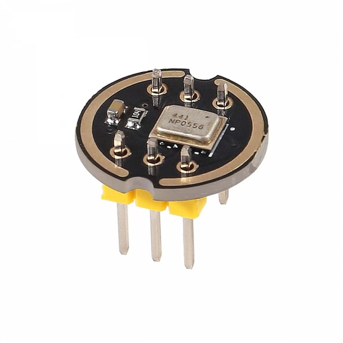
INMP441 MEMS Microphone Module- I2S interface
$3.8700
In stock
SKU
SEN-17-149
Volume discounts:
- +25 3 % $3.7400
- +100 5 % $3.6800
- +300 7 % $3.6100
- +500 8 % $3.5500
- +1000 10 % $3.4800
Ships in 2-3 business days, then:
Free delivery in 12-15 days by Tracked Economic Shipping on orders over $100.
Free delivery in 7-10 days by Express Shipping on orders over $300.
More shipping info

Shop with confidence Learn More
 JQ6500 MP3 Voice Module Previous
INMP441 I2S Microphone Overview
The INMP441 MEMS Microphone Module is an omnidirectional digital sound sensor that outputs 24-bit audio data over an I2S interface. It connects directly to digital signal processors, microcontrollers, and single-board computers without an external audio codec. For hardware builds that need serial digital sound capture, it combines an integrated microphone element with a bottom acoustic port. This module is designed for 3.3V digital audio systems; it does not produce an analog voltage signal and must not be connected to 5V power rails.
For complementary capture hardware, browse related sound modules.
Specifications of INMP441 MEMS Microphone Module- I2S interface
- Type: Sound Sensor
- Microphone type: MEMS
- Microphone model: INMP441
- Interface: I2S
- Digital I2S interface with high precision 24-bit data
- Frequency response: 100 Hz to 20 kHz
- Frequency response: 60 Hz to 15 kHz
- Sensitivity: -26 dBFS (0 dBFS = 94 dB SPL)
- Sensitivity: -26 dBFS
- Signal-to-noise ratio: 63 dB
- Signal-to-noise ratio: 61 dBA
- Operating voltage: 1.8 V to 3.6 V
- Input power: 1.8 V to 3.3 V
- Current consumption: 500 microamps
- Low current consumption: 1.4 mA
- PSR: -75 dBFS
- Dimensions: 5 x 3.76 x 1 mm
- Pins: SCK
- Pins: WS
- Pins: L/R
- Pins: VCC
- Pins: GND
- SCK: Serial data clock for I2S interface
- WS: Serial data word selection for I2S interface
- L/R: Left/Right channel selection
- VCC: Input power, 1.8 V to 3.3 V
- GND: Power ground
- VDD: 3v3 Power
- VDD: Do not use 5V
- GND: GND
- L/R: GND Left channel or right channel
- WS: 22 Left right clock
- SCK: 26 Serial clock
- SD: 21 Serial data
INMP441 I2S Microphone Pinout and Compatibility
Connecting the INMP441 requires six electrical lines: power, ground, and four digital audio signals. The serial clock (SCK) synchronizes data bit shifts, while the word select line (WS) sets frame timing between left and right audio channels. Serial data (SD) sends the digitized 24-bit audio stream to the host processor. The L/R pin controls channel configuration: connecting L/R to ground assigns data to one channel, while tying it to the supply rail directs it to the opposite channel. Leaving L/R unconnected can cause unstable channel assignments or intermittent data drops.
The host processor needs a dedicated hardware I2S peripheral. Microcontrollers such as the ESP32 and STM32 family, along with single-board computers such as the Raspberry Pi, interface directly with these lines. Microcontrollers without hardware I2S, including the Arduino Uno and Nano, cannot process the serial audio stream without external conversion hardware. Technical reference sheets cite WS on GPIO 22, SCK on GPIO 26, and SD on GPIO 21 as a common ESP32 wiring mapping. This is an implementation example, not a fixed hardware restriction; ESP32 GPIO routing allows reassignment to other suitable digital pins in software.
For microcontrollers that accept only analog inputs, the CJMCU MAX9814 AGC Microphone Amplifier takes a different approach, providing analog microphone output with automatic gain control. Initial INMP441 testing requires six stable connections, which can be routed with a Breadboard Jumper Wire Kit - 140 Pieces.
INMP441 I2S Microphone Specifications Explained
I2S is a synchronous serial protocol designed specifically for streaming audio. It uses dedicated clock lines rather than an address-based bus structure, so it cannot be wired to standard I2C data (SDA) or clock (SCL) pins. The module outputs 24-bit audio samples. To avoid bit shifts and distorted waveforms, configure the host controller's firmware driver for matching 24-bit or 32-bit slot widths.
The integrated MEMS element defines acoustic performance. Its physical silicon has a frequency response spanning 60 Hz to 15 kHz at -3 dB points, providing targeted voice-band capture with a sensitivity of -26 dBFS at 94 dB SPL. An A-weighted signal-to-noise ratio of 61 dBA and a power supply rejection ratio of -75 dBFS help maintain low background hiss when the module receives clean power. Current draw remains low: roughly 1.4 mA at 1.8 V, rising toward 2.2 mA under 3.3 V rails.
Physical integration depends on the bottom-port construction. Sound enters through an aperture on the underside of the MEMS package and through a matching hole in the breakout board. The listed dimension of 5 x 3.76 x 1 mm describes the surface-mount MEMS package rather than the outer carrier board, which varies across production lots. For another digital sensor option, the ADMP441 MEMS Microphone is a 24-bit I2S MEMS microphone with similar voice-band acoustic characteristics.
| Specification | Technical Value | Why It Matters |
|---|---|---|
| Interface | I2S (Inter-IC Sound) | Transmits uncompressed digital audio directly to processor memory without an intermediate ADC or codec. |
| Data Depth | 24-bit serial output | Provides high sample resolution, though firmware I2S drivers must be set to compatible bit-slot widths. |
| Acoustic Response | 60 Hz to 15 kHz (-3 dB) | Tailored for speech recognition and ambient monitoring; rolls off ultrasonic and sub-bass frequencies. |
| Sensitivity | -26 dBFS (at 94 dB SPL, 1 kHz) | Defines digital signal output level relative to full scale under standard conversational sound pressures. |
| SNR & PSR | 61 dBA SNR, -75 dBFS PSR | Maintains clean voice capture and suppresses electrical ripple coming from system power lines. |
| Acoustic Port | Bottom-port configuration | Requires an open, unobstructed pathway beneath the PCB to allow sound waves to reach the sensor cavity. |
INMP441 I2S Microphone Limitations and Setup Risks
The most critical setup hazard is input voltage. The INMP441 operates between 1.8 V and 3.3 V, with an absolute maximum limit of 3.63 V. Supplying 5V directly to VDD will permanently destroy the MEMS chip. Where multiple rail voltages are present during bench prototyping, power the board only from the 3.3V rail of a Breadboard Power Supply Module - 3.3V/5V to avoid accidental overvoltage.
Signal-processing options are fixed in hardware. The module has no onboard analog gain potentiometer or automatic gain adjustment; any signal scaling or filtering must be handled in microcontroller software. Projects that specifically need adjustable analog microphone gain can use the MAX4466 Adjustable Microphone Amplifier, an analog alternative with a physical potentiometer.
- After power initialization, the internal digital modulator needs time to stabilize. Firmware should discard the first 85 ms of captured audio data to prevent loud DC pops or corrupt sample frames.
- Clean power is essential. The IC design recommends placing a 0.1 µF ceramic decoupling capacitor across VDD and GND near the sensor. Because generic breakout boards do not always include this capacitor, adding one externally protects against logic switching noise.
- Mechanical enclosures must align with the bottom port. Mounting the board flush against a solid panel blocks the acoustic path entirely.
INMP441 I2S Microphone Projects and Uses
The INMP441 is widely used in connected audio applications built around 32-bit microcontrollers. In local voice control, edge AI frameworks use its digital stream to process wake-word models directly on an ESP32. For remote monitoring, raw audio samples can be packaged into UDP packets and streamed over WiFi to central recording servers. Sound-level monitoring stations benefit from direct digital data, allowing software to calculate calibrated decibel readings without analog ADC drift.
Multi-channel setups are straightforward. Two INMP441 modules can share common SCK and WS clock lines on a single microcontroller I2S bus. Tie the L/R pin of the first board to ground to route its data to the left channel, then tie the second board's L/R pin to 3.3V to direct its stream to the right channel. Together, they form a synchronized stereo capture array.
A MB-102 Breadboard - 165x55x10mm provides sufficient bus lines for clock distribution and local decoupling when prototyping these multi-wire circuits. For builds that combine sound input and playback, Interfacing UDA1334A I2S Stereo Decoder Module with ESP32 covers a full ESP32 I2S input-and-output audio system.
INMP441 I2S Microphone vs Analog Microphone Modules
The right microphone module depends on your host processor's peripheral support and signal requirements. The INMP441 includes an analog-to-digital converter and outputs serial data that resists electromagnetic noise across longer prototype leads. Analog modules produce a varying voltage that must be sampled by an external microcontroller ADC.
| Feature | INMP441 Module | MAX9812L Module | CJMCU MAX9814 Module | MAX4466 Module |
|---|---|---|---|---|
| Output Type | Digital I2S (24-bit) | Analog voltage | Analog voltage | Analog voltage |
| Gain Control | Fixed internal | Fixed 20 dB | Automatic Gain Control (40/50/60 dB) | Manual trim pot (25x to 125x) |
| Operating Voltage | 1.8 V to 3.3 V (No 5V) | 2.7 V to 3.6 V | 2.7 V to 5.5 V | 2.4 V to 5.5 V |
| Host Requirement | Hardware I2S peripheral | Standard analog ADC pin | Standard analog ADC pin | Standard analog ADC pin |
| Best Architecture | ESP32, STM32, Raspberry Pi | Compact fixed-gain analog builds | Variable-volume environments | Manually calibrated analog builds |
Systems without an I2S controller have practical analog options. The MAX9812L Microphone Amplifier supplies basic fixed-gain analog preamplification in a compact footprint. Where acoustic levels fluctuate significantly, the CJMCU MAX9814 AGC Microphone Amplifier dynamically normalizes output through automatic gain control. For projects that need manual signal leveling before an ADC, the MAX4466 Adjustable Microphone Amplifier allows direct sensitivity calibration through an onboard potentiometer.
INMP441 I2S Microphone FAQ
Will the INMP441 I2S microphone work with Arduino Uno?
No. The Arduino Uno lacks the hardware I2S peripheral needed to decode serial digital audio streams. Use an I2S-capable board such as an ESP32, STM32, or Raspberry Pi instead.
Can the INMP441 I2S microphone connect to 5V?
No. Connecting 5V to VDD will permanently damage the module. Its operating input range is strictly 1.8 V to 3.3 V.
Is the INMP441 an analog microphone?
No. The INMP441 outputs only digital I2S serial audio data. For analog projects, consider the CJMCU MAX9814 AGC Microphone Amplifier or the MAX4466 Adjustable Microphone Amplifier.
Why does an INMP441 I2S microphone produce silence on an ESP32?
Silence usually results from unconfigured GPIO assignments, missing 3.3V power, an ungrounded L/R pin, or mismatched software I2S driver settings. Check connections with a Breadboard Jumper Wire Kit - 140 Pieces, then verify that your firmware expects the specific channel and slot width wired to the board.
Does the INMP441 L/R pin need to be connected?
Yes. Tie the L/R pin to either GND or VDD to establish whether the microphone outputs on the left or right channel. Leaving it floating causes undefined channel behavior or missing data.
Where is the INMP441 microphone sound port?
The sound inlet is on the underside of the MEMS package and routes through an opening in the circuit board. Enclosures and mounting hardware must leave this hole clear for audio capture.
What are the actual INMP441 module dimensions?
The listed 5 x 3.76 x 1 mm figure describes the surface-mount MEMS IC package, not the breakout PCB. Carrier board dimensions depend on the manufacturing batch.
What is the difference between I2S and I2C for the INMP441 microphone?
I2S is a continuous streaming protocol designed specifically for digital audio transmission, while I2C is a shared bus protocol used for register communication. The INMP441 cannot communicate over I2C data or clock lines.
Purchase Decision Summary
- Ideal for: ESP32, STM32, Raspberry Pi, and DSP systems requiring direct 24-bit digital audio streaming without an external ADC or audio codec.
- Maybe for: Intermediate builders comfortable configuring I2S clock and frame parameters in code, supplying 3.3V logic, and designing enclosure openings around a bottom sound port.
- Consider another option if: You are using an Arduino Uno or other microcontroller without hardware I2S, require an analog voltage output, operate strictly on 5V power rails, or need acoustic capture beyond 15 kHz.
Buying Checklist
- Confirm your host microcontroller includes a dedicated hardware I2S peripheral.
- Ensure your circuit provides a regulated 1.8 V to 3.3 V power supply and prevents 5V contact.
- Verify your software stack supports I2S digital audio rather than analog ADC sampling.
- Plan for six connections: VDD, GND, SCK, WS, SD, and L/R channel select.
- Verify physical pin labels on the carrier board before wiring power lines.
- Allow for an unobstructed acoustic opening beneath the board in your enclosure design.
- Note that 5 x 3.76 x 1 mm refers to the IC package, not the outer breakout PCB footprint.
- Program your firmware to discard the first 85 ms of audio samples after power-up.
- Add a breadboard, jumper leads, and a dedicated 3.3V supply to your order if needed.
- Choose an analog preamplifier board if your hardware requires an analog voltage signal.
| Interface Type | Digital |
|---|---|
| Operating Voltage (V) | 1.8 to 3.3V |
| Operating Current (mA) | 0.6 to 1.4 mA |
| Operating Temp (°C) | -40 to 85 |
| Dimensions (mm) | 5 x 3.76 x 1 |
| Audio Function | Microphone |
| Input Types | MEMS |
| Bluetooth Ver. | No |
| Output Type | Digital |
| Channels | 1-channel |
| Chipset | INMP441 |
| Frequency Response | 60 Hz to 15 kHz (up to 20 kHz) |
Write Your Own Review

Please complete your information below to login.
Sign In
Create New Account