
Product added to cart

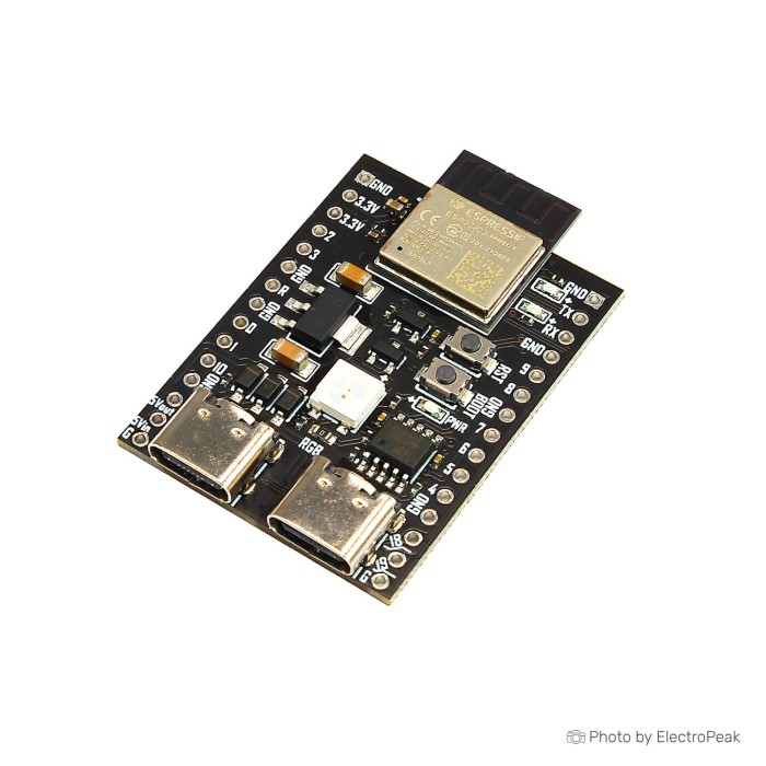
ESP32-C3 Dual USB Port
$10.9500
In stock
SKU
COM-03-097
Volume discounts:
- +25 4 % $10.5400
- +50 6 % $10.3400
- +100 7 % $10.1300
- +300 9 % $9.9300
- +500 11 % $9.7200
Ships in 2-3 business days, then:
Free delivery in 12-15 days by Tracked Economic Shipping on orders over $100.
Free delivery in 7-10 days by Express Shipping on orders over $300.
More shipping info

Shop with confidence Learn More
 Espressif ESP32-WROOM-32D Module ( Wifi + Bluetooth) Previous
The ESP32-C3 Dual USB Port Development Board is a general-purpose Wi-Fi and Bluetooth LE development board built around an ESP32-C3 module. It provides dual USB Type-C connectors for flexible connection options. The board breaks out most I/O pins to side headers for external interfacing. It includes an RGB WS2812 user LED and a power LED for board-level indication and lighting control. This ESP32-C3 Dual USB Port Development Board is designed with onboard support for debugging and firmware upgrade through the CH340 virtual USB port.
Features of ESP32-C3 Dual USB Port Development Board
- 2.4 GHz Wi-Fi support
- Bluetooth 5 support
- Bluetooth mesh support
- 4 MByte SPI Flash
- 384 KByte ROM
- 400 KByte SRAM
- PCB antenna
- Dual Type-C USB connectors
- Reset button
- User/Firmware buttons
- RGB WS2812 user LED
- Power LED
- CH340 virtual USB port
- ESP32-C3 module assembly
- Side pin headers
- Compact board size
Specifications of ESP32-C3 Dual USB Port Development Board
- Supply Voltage: 5V via USB
- Circuit Voltage: 3.0 to 3.6V
- Wi-Fi: IEEE 802.11 b/g/n
- Bluetooth: Bluetooth 5
- Bluetooth: Bluetooth mesh
- Flash: 4 MByte (32Mbit) SPI Flash
- ROM: 384 KByte
- SRAM: 400 KByte
- Dimensions: 35.6 x 30
- USB connectors: Dual Type-C USB
- USB interface: CH340 virtual USB port
- LED: RGB WS2812 user LED
How to Use ESP32-C3 Dual USB Port Development Board
- Connect the board to power through a USB Type-C connector.
- Use the side pin headers to connect external devices or wiring.
- Use the CH340 virtual USB port for debugging or firmware upgrade.
- Use the reset and user/firmware buttons as needed during development.
More Info
- Most I/O pins are broken out to headers on both sides.
- The board is assembled with an ESP32-C3 module.
- The RGB WS2812 LED is connected to IO8.
| MCU/SoC | ESP32-C3 |
|---|---|
| Product Family | ESP32 |
| Architecture | RISC-V |
| CPU Cores | Single-core |
| Clock Speed (MHz) | 160 MHz |
| Flash | 4 MB |
| SRAM | 400 KB |
| SPI interface Pins | 3 |
| I2C interface Pins | 1 |
| UART interface Pins | 2 |
| USB Ports | 2 |
| CAN Bus Support | Yes (TWAI) |
| Ethernet Support | No |
| ADC Channels | 6 |
| DAC Channels | 0 |
| PWM Channels | 6 |
| Timers Count | 3 |
| Operating Voltage (V) | 5V |
| GPIO Voltage (V) | 3.3V |
| Wireless | Wi-Fi, Bluetooth mesh, Bluetooth LE |
| Form Factor | 35.6 x 30 mm |
| IDE Support | MicroPython, Arduino, ESP-IDF |
| Input Voltage (V) | 5V via USB |
| Antenna Type | Internal Antenna |
| Bluetooth Ver. | 5 |
Write Your Own Review

Please complete your information below to login.
Sign In
Create New Account