
Product added to cart

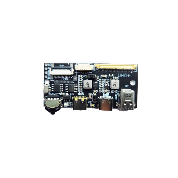
4K-144HZ/2K-240Hz/1080P-480Hz DP to EDP Display Driver Board
$18.9500
In stock
SKU
LCD-02-005
Volume discounts:
- +25 4 % $18.2000
- +50 6 % $17.8300
- +100 8 % $17.4600
- +300 10 % $17.0900
- +500 12 % $16.7100
Ships in 2-3 business days, then:
Free delivery in 12-15 days by Tracked Economic Shipping on orders over $100.
Free delivery in 7-10 days by Express Shipping on orders over $300.
More shipping info

Shop with confidence Learn More
 DP to EDP 30/40PIN Display Driver Board 2k-165hz 4k-144hz Previous
DP to eDP Driver Board Review
This is a bare MiniDP-to-eDP display controller for DIY builders integrating a verified compatible laptop panel. At US$18.50, it suits compact portable-monitor and high-refresh display builds where space is limited. It is intended for technically confident builders who can verify panel signaling, pinouts, and power demands independently—not buyers seeking a plug-and-play monitor conversion kit with guaranteed panel compatibility, onboard audio, or HDMI convenience.
Specifications of 4K-144HZ/2K-240Hz/1080P-480Hz DP to EDP Display Driver Board
- Products support FHD+,QHD+,UHD+ and other mainstream resolution TFT LCD screens, such as BOE, Auo, Sharp, Huaxing Optoelectronics, LG, Samsung and other brands of pen EDP signal type LCD screen.
- Screen Interface Type: eDP HRB,eDP HRB2 (40PIN 4lanes EDP)
- PCB size: 60x28mmx5.5mm(PCB board thickness 1.2mm)
- LCD resolution MAX:3840x2160@144HZ/2560X1600@240HZ/2560X1440@240HZ/1080P@480HZ
- External input interface: MiniDP, miniHDMI(no features), Typec1(PD), Typec 2(TP)
- Power input: 5V3A /PDOC:9V3A-12V3AUSB:5V1A Select power according to screen power *1.3 times
- Power operation: Normal working mode, low power standby mode
- Power management: standby power consumption ≤1W, in line with national green standards
- OSD language: None
- Key type: GPIO to the ground
- Number of keys: 3 keys
- Button description: Power CH-CH+
- Screen line interface: 20455-40P(support 40P30P LCD screen)
For other display interface standards or panel types, see our wider selection of LCD driver boards.
DP to eDP Board 4K 144Hz Specifications Explained
The listed specifications matter most when translated into enclosure constraints, display-link requirements, and day-to-day operating limits. Here is how the key figures affect the display pipeline and physical integration.
| Specification | Listed Value | Why It Matters |
|---|---|---|
| Max Advertised Display Modes | 3840x2160@144Hz, 2560x1600@240Hz, 2560x1440@240Hz, 1080P@480Hz | These figures represent advertised upper timing limits. Reaching them in practice depends on GPU link capabilities, cable quality, panel timing tolerances, and the specific controller revision. They should not be treated as a guarantee for every panel pairing. |
| Board Dimensions | 60 × 28 × 5.5 mm (1.2 mm PCB thickness) | The narrow 28 mm profile allows mounting directly behind a slim panel or inside shallow enclosures. Adequate standoffs are necessary to isolate the exposed solder joints from metallic panel chassis. |
| Display Output Interface | eDP HRB, eDP HRB2 (40-pin 4-lane eDP) | High Bit Rate (HBR) and HBR2 support across 4 lanes provides the bandwidth necessary for high-density, high-refresh panels. It requires an exact matching 40-pin wiring harness; mechanical fit alone does not guarantee electrical compatibility. |
| Controls & OSD | 3 GPIO-to-ground keys (Power, CH-, CH+); OSD Language: None | With no on-screen display menu, the board does not offer traditional monitor adjustments for brightness, contrast, color temperature, or input switching. Hardware controls are limited to basic power and channel cycling. |
| Power Management | Normal working mode, low power standby mode (≤1W) | The board implements an idle state drawing 1W or less to meet baseline efficiency standards when no active video source is present. |
For an equivalent listing option based on availability or packaging preference, see the DP to EDP 30/40-Pin Driver Board, which shares the same fundamental specifications. For a source-side DisplayPort connection, use a verified link such as the DisplayPort Cable 8K/60Hz with the appropriate adapter or MiniDP interface.
40-Pin eDP Panel Compatibility and Limits
Screen size and brand name alone cannot establish compatibility with this board. The specifications name BOE, AUO, Sharp, CSOT (Huaxing Optoelectronics), LG, and Samsung panels, but electrical compatibility depends on the panel's internal pin assignment, logic voltage, backlight circuit demand, AUX/HPD routing, and data lane configuration.
The output is specifically eDP (Embedded DisplayPort). It is not compatible with legacy LVDS (Low-Voltage Differential Signaling) laptop panels, which use fundamentally different signaling protocols and voltage levels. Connecting an LVDS panel will result in a black screen or electrical damage.
Input connectivity needs the same level of scrutiny:
- MiniDP: The board's primary documented video input.
- miniHDMI: Listed explicitly as miniHDMI(no features). Do not rely on this port for active video input.
- Type-C1: Designated as PD (Power Delivery). USB-C DisplayPort Alternate Mode video is undocumented for this board; treat this connector strictly as a power input.
- Type-C2: Designated as TP (Touch Panel). The board is sold with touch support, but an external compatible touch controller is required to route digitizer data back to your host. Operating system compatibility and touch protocol support are not documented.
Select power according to the rule Screen Power × 1.3. The board lists power input ratings of 5V3A / PDOC:9V3A-12V3A / USB:5V1A. Maximum continuous wattage is not formally published, so verify your panel's combined logic and backlight draw before choosing an adapter such as a 12V 3A Wall Power Adapter.
30-pin panel support remains unclear. Although the connector is documented as 20455-40P(support 40P30P LCD screen), no 30-pin wiring diagram, breakout pinout, or adapter hardware is documented. Treat 30-pin support as unverified until hardware documentation confirms it. Audio pass-through is also undocumented for this board, so plan separate audio routing.
For native multi-input switching across modern sources instead of a dedicated MiniDP connection, consider the 4K 120Hz/165Hz Driver Kit (Type-C/Mini DP/Mini HDMI), which documents Type-C, Mini DP, and Mini HDMI inputs. For an eDP panel connection, verify pitch and pin assignments against the EDP FFC Flexible Cable With I-PEX Metal Head 0.5 pitch 30P/40P. Use a dedicated 30P Multi-Length EDP Screen Cable only after independently verifying 30-pin wiring.
DP to eDP Driver Board Setup Check
Before mounting the driver board inside a custom chassis or applying permanent adhesive, run an external bench test to confirm display detection and timing stability.
- Identify Panel Model: Find the exact model number on the barcode label on the back of your LCD panel. Obtain the manufacturer datasheet.
- Verify Signaling: Confirm in the datasheet that the panel uses a 40-pin eDP interface (HBR/HBR2, 4 lanes) rather than LVDS. Note the logic voltage (typically 3.3V) and backlight supply requirements.
- Check Cable Pinout and Orientation: Align the EDP FFC Flexible Cable so Pin 1 on the driver board matches Pin 1 on the panel connector. Misalignment can damage the panel's timing controller.
- Connect Panel with Power Off: Fully seat the eDP cable in both the driver board and panel while all power sources are disconnected. Secure any connector latches.
- Attach Video Source: Connect your source device to the MiniDP port with a verified cable such as the DisplayPort Cable 8K/60Hz and an appropriate MiniDP connector.
- Apply Power: Connect a power supply meeting the
Screen Power × 1.3threshold, such as a 12V 3A Wall Power Adapter, depending on the confirmed revision and board input mode. - Establish Baseline Signal: Power on the host system and confirm that the operating system detects an external display. Start at a standard 1080p 60Hz timing before attempting high-refresh or high-resolution modes.
- Validate Controls and Touch: Test the Power, CH-, and CH+ GPIO switches. For a touch panel, route the touch digitizer cable to the Type-C2 TP port and confirm host input.
Expected Result: The host graphics card enumerates the display through the DisplayPort AUX channel, the backlight illuminates evenly, and an artifact-free desktop image appears. Common early failures include connecting video to the Type-C1 PD port, which carries no video signal, underpowering the backlight inverter, or reversing the eDP cable orientation.
DP to eDP Driver Board Accessories and Required Parts
Because package contents are not stated in the product data, plan on purchasing a bare printed circuit board. A complete display build requires several complementary hardware components.
Required Hardware
- Compatible eDP LCD Panel: A verified 40-pin 4-lane eDP panel matching the board's electrical interface.
- Verified eDP Panel Cable: Use a suitable harness such as the EDP FFC Flexible Cable With I-PEX Metal Head 0.5 pitch 30P/40P. Verify pin assignments against your panel's datasheet.
- Suitable Power Supply: Size the supply to provide at least 1.3 times the panel's combined power draw. Depending on the configuration, options include the 12V 2A Wall Power Adapter for smaller screens or the higher-capacity 12V 3A Wall Power Adapter for larger, high-brightness panels.
- MiniDP Video Cable: A high-bandwidth DisplayPort interconnect, such as the DisplayPort Cable 8K/60Hz, matched to the MiniDP port.
- Mechanical Insulation: Non-conductive standoffs or an insulated backing plate to prevent short circuits against the bare PCB.
Recommended Items
- Panel Datasheet: Complete technical documentation confirming voltage, lane allocation, and backlight limits.
- 30-Pin eDP Cable: The 30P Multi-Length EDP Screen Cable, only for builders who have independently verified 30-pin signaling on their hardware revision.
- Inline USB-C / DC Power Meter: For measuring continuous current draw and confirming voltage-rail stability under peak backlight load.
- Bench Test Rig: A non-conductive testing mat for evaluating signal integrity before permanent assembly.
Optional Items
- Touch Interface Cabling: A dedicated USB harness connecting the host to the Type-C2 TP port when integrating a touch digitizer.
- Custom Enclosure / Frame: An acrylic, 3D-printed, or CNC-milled chassis for the panel, board, and button harness.
- External Audio Hardware: A USB sound card, external amplifier, or DAC, since onboard audio routing is not documented.
For non-eDP panels, including standard digital TTL or LVDS screens recovered from older monitors, this eDP board cannot be used. A different architecture, such as the RTD2660 HDMI/VGA/AV to LVDS/RGB/TTL Converter, provides the appropriate legacy signaling paths for those displays.
DP to eDP Driver Board vs Multi-Input Driver Kit
The choice between a bare MiniDP board and a fully featured driver kit comes down to your source hardware, refresh requirements, and integration goals.
| Feature / Specification | LCD-02-005 (This Board) | DP to EDP 30/40-Pin Driver Board | 4K 120Hz/165Hz Driver Kit (Type-C/Mini DP/Mini HDMI) |
|---|---|---|---|
| Listing Relationship | Base model review | Equivalent listing | Variant kit |
| Active Video Inputs | MiniDP documented (miniHDMI listed with no features) | MiniDP documented | Type-C, Mini DP, Mini HDMI documented |
| Max Advertised Modes | 4K@144Hz, 2K@240Hz, 1080p@480Hz | 4K@144Hz, 2K@165Hz advertised | Up to 1080p@300Hz, 2K@165Hz, 4K@120Hz/165Hz |
| Touch Integration | Type-C TP port listed | Touch support listed | Touch support documented with multi-input routing |
| Power Input Method | 5V3A / PDOC:9V3A-12V3A / USB:5V1A | 5V / PD / DC input ranges | Fast charging power supply (>65W required) |
| Best Application | Compact, single-source MiniDP builds with high-refresh panels | Direct substitute based on local stock availability | Multi-device setups needing HDMI, Type-C video, and MiniDP |
Custom panel-specific driver kits, pre-flashed for a particular panel model, minimize integration risk but are often locked to a single resolution. At US$18.50, this board offers flexibility across multiple high-refresh eDP timing profiles, provided you can supply a compatible MiniDP signal and a verified panel pinout.
DP to eDP Driver Board FAQ
Will this DP to eDP driver board work with my 40-pin laptop screen?
Only if your screen uses an eDP HRB or HRB2 4-lane interface with matching electrical pinouts. A 40-pin connector alone does not guarantee compatibility because power rails, ground assignments, and backlight pins differ among panel designs. Verify your panel's datasheet before connection.
Is the video input full-size DisplayPort or MiniDP?
The documented video input is MiniDP. It does not have a full-size DisplayPort receptacle. If your graphics card uses standard DisplayPort, you will need a DisplayPort-to-MiniDP cable or passive adapter.
Can I use USB-C for video with this eDP driver board?
No. The Type-C1 port is documented as PD for power delivery, while Type-C2 is designated as TP for touch data. USB-C DisplayPort Alternate Mode video is not documented for this board. For native USB-C video input alongside HDMI and DisplayPort, consider the 4K 120Hz/165Hz Driver Kit (Type-C/Mini DP/Mini HDMI).
Does this board support 30-pin eDP panels?
The screen interface specification notes support 40P30P LCD screen, but no 30-pin pinout, wiring guide, or adapter hardware is documented. Treat 30-pin compatibility as undocumented until it is verified with specific technical drawings.
Can I use an LVDS laptop panel?
No. This controller is designed strictly for eDP signaling. LVDS displays use different signal voltages and serializing methods, so they are not electrically compatible with this board.
Can it run 4K at 144Hz, 2K at 240Hz, or 1080p at 480Hz?
These are the advertised maximum modes in the controller specifications. Achieving those refresh rates requires a panel natively rated for the timings, an uncompressed high-bandwidth GPU DisplayPort output, high-grade cabling, and compatible controller firmware timing tables.
What power supply does the board need?
The board specifications list 5V3A / PDOC:9V3A-12V3A / USB:5V1A and instruct you to size the supply to at least 1.3 times the panel's rated power consumption. Verify the voltage input mode for your specific board revision before applying power.
Are the eDP cable and power adapter included?
Package contents are not stated in the website data. Plan on the board shipping as a bare PCB, requiring a separately sourced power supply, MiniDP cable, and EDP FFC Flexible Cable.
Does the board support touch?
The board is listed with touch support and provides a Type-C2 TP interface. It does not include a touch digitizer screen. You must supply a compatible touch panel and controller, routing data through the TP port to your host machine.
Does it have audio output or a full OSD menu?
No audio output is documented for this board, so plan separate audio connections. The OSD language is listed as None, meaning there is no traditional graphical on-screen menu for adjusting color balance or brightness levels.
Does it need an operating system driver?
Display communication operates over standard VESA DisplayPort protocols, so no proprietary display drivers are required on the host system. Operating system compatibility for the touch interface data path is not documented.
Is the manufacturer, controller IC, or PCB revision known?
The board is cataloged without a published manufacturer datasheet, controller IC part number, or firmware revision history. Builders should rely on empirical bench testing before final enclosure integration.
Purchase Decision Summary
- Ideal for: Experienced electronics builders creating a compact portable monitor around a known, verified 40-pin 4-lane eDP laptop panel with a MiniDP source.
- Maybe for: Touch kiosk prototypes or test fixtures where the builder can independently supply and verify the touch controller, power budget, and panel pin assignments.
- Consider another option if: Your panel uses LVDS signaling, your primary source is HDMI or USB-C DisplayPort Alt Mode, you require integrated monitor speakers, or you need guaranteed 30-pin panel compatibility out of the box.
Buying Checklist
- I have identified the exact part number from my panel's rear label.
- I have verified via the panel datasheet that it uses 40-pin eDP, not LVDS.
- I have checked panel voltage, backlight requirements, and connector pinout orientation.
- I understand that a matching 40-pin physical connector does not ensure compatibility.
- I have verified that my video source outputs via native MiniDP or a verified DP-to-MiniDP link.
- I am not planning to use the miniHDMI port or Type-C1 PD port for video input.
- I have chosen a power supply providing at least 1.3× my panel's total wattage.
- I have accounted for separate eDP cables, power adapters, and chassis mounting hardware.
- I have planned a separate audio path if my build requires sound.
| Interface Type | Digital, USB, HDMI |
|---|---|
| Dimensions (mm) | 60 x 28 x 5.5 |
| Interface Category | eDP |
| Keys Count | 3 |
| Output Type | Digital |
| Voltage Range | 5V 3A / PD: 9V 3A-12V 3A, USB: 5V 1A |
| Protocols | DP |
| Conversion Type | DP to EDP |
Write Your Own Review

Please complete your information below to login.
Sign In
Create New Account