
Product added to cart

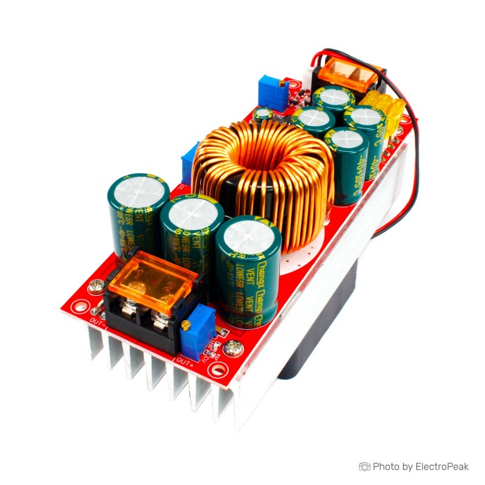
DC/DC Step-Up Regulator Module - 1500W, 30A
$10.9500
In stock
SKU
BAT-02-104
Volume discounts:
- +25 4 % $10.5100
- +50 6 % $10.2900
- +100 8 % $10.0700
- +300 10 % $9.8500
- +500 12 % $9.6400
Ships in 2-3 business days, then:
Free delivery in 12-15 days by Tracked Economic Shipping on orders over $100.
Free delivery in 7-10 days by Express Shipping on orders over $300.
More shipping info

Shop with confidence Learn More
 DC/DC Step-Down Regulator Module - 300W, 20A Previous
1500W 30A Boost Converter Review
This manually adjustable DC-to-DC boost module raises a 10–60V DC source to a higher-voltage load between 12V and 97V. Built around dual toroidal inductors wound with 1.2mm wire, it includes an integrated aluminum heatsink, a temperature-controlled cooling fan, and three multi-turn potentiometers for constant-voltage, constant-current, and undervoltage-lockout adjustment. It suits builders using 12V, 24V, 36V, or 48V supplies who have the bench tools to verify wiring, source current, and operating temperatures before connection.
This is strictly a step-up converter. It cannot regulate voltage downward, does not isolate input ground from output ground, and will not deliver 1500W continuous output from low-voltage sources such as 12V batteries. For projects requiring step-down or bi-directional conversion, review the broader range of DC-DC regulator modules before finalizing a build.
Specifications of DC/DC Step-Up Regulator Module - 1500W, 30A
- Material: metal
- Size: 130*52*84mm
- Input voltage range: DC 10V~60V
- Input current: 10~30V input voltage, maximum current 35-40A
- Input current: 31~60V input voltage, maximum current 30-35A
- Static operating current: 15 mA
- Output voltage: 12~97V continuously adjustable
- Output current: 22A MAX
- Output current note: more than 15A please enhance heat dissipation
- Constant current range: 0.8~22A (±0.3A)
- Operating frequency: 150 KHz
- Conversion efficiency: 92% ~ 97%
- Output voltage default: 19V
- Input current: 30A (10-30V input)
- Input current: 25A (31-60V input)
- Static operating current: 15 mA
- Under voltage threshold range: DC10V-50V
- Output voltage adjustable range: DC12-97V
- Constant current adjustable range: 0.8-22A
1500W 30A Boost Converter Specifications Explained
Understanding how the electrical ratings work together helps prevent component damage and unrealistic power expectations during system integration.
| Specification | Documented Value | Why It Matters |
|---|---|---|
| Input Voltage Range | DC 10V~60V | Accommodates common DC systems including 12V lead-acid, 24V industrial rails, and 36V or 48V battery banks. Voltages below 10V trigger instability or cutoff. |
| Output Voltage Range | DC 12~97V (continuously adjustable) | The target output must remain higher than the active input voltage. The factory default setting is 19V, so the output must be measured and set before attaching a load. |
| Input Current Limits | 30A (10–30V) / 25A (31–60V); Peak 35–40A / 30–35A | Input current is distinct from output current. Low input voltages draw high current to deliver moderate wattage, requiring heavy cabling and low source impedance. |
| Output Current Limits | 22A MAX; 0.8–22A CC range (±0.3A) | Sets the maximum current the module can deliver to a load. Loads drawing above 15A require active external airflow beyond the onboard fan. |
| Conversion Efficiency | 92% ~ 97% | Efficiency varies heavily with the difference between input and output voltage. Stepping 12V up to 80V yields higher thermal dissipation and lower net efficiency than stepping 48V to 60V. |
| Switching Frequency | 150 KHz | Standard high-frequency power switching balances inductor physical size against switching losses, though high-current ripple requires bypass capacitance on noise-sensitive loads. |
| Physical Envelope | 130 * 52 * 84 mm | The tall height profile (84mm) is dictated by the cooling fan and heavy heatsink. Adequate enclosure clearance must be budgeted to allow unhindered intake and exhaust airflow. |
1500W 30A Boost Converter Limits and Safety
The 1500W designation represents a theoretical ceiling under ideal, high-voltage conditions, not a continuous rating across all voltages. Input voltage directly limits total delivered power. Power equals voltage multiplied by current: a 12V supply delivering 30A into the module supplies 360W of total input power. After thermal conversion losses, available output power remains well under 350W. Reaching several hundred watts requires a 36V, 48V, or 60V supply.
High current produces substantial heat across the switching transistors, inductors, and terminal blocks. Enhanced heat dissipation is required whenever output current exceeds 15A. Builders adding auxiliary conduction cooling can fit small components such as a 20x15x10mm Aluminum Heatsink - Black onto uncooled passive board areas, but primary thermal relief depends on unobstructed airflow across the main finned assembly.
Wiring integrity is a practical safety priority. Sustained input currents of 25A to 30A require thick, short copper cables to limit resistive voltage drop and localized terminal heating. For battery banks connected through quick-disconnect plugs, rated connectors such as an XT60 Connector Male-Female Pair for LiPo Battery can be used provided the continuous system amperage remains within connector limits. External branch fusing on the source wiring is recommended; the onboard 30A fuse protects against catastrophic internal board failure rather than branch-circuit overloads.
The module includes input reverse-polarity protection via MOS circuitry, an onboard 30A fuse, and double short-circuit protection. Output polarity cannot be reversed, and the output terminals must not be shorted. Although short-circuit protection is present, running boost converters into a continuous output dead short stresses components and must be avoided. If your input voltage can fluctuate both above and below the desired output, use an XL6009 Buck-Boost Module instead of this step-up board.
This design shares a common ground between input and output. It provides no galvanic isolation. Ground loops can form when the module shares a common negative return with sensitive microcontroller signaling or vehicle chassis grounds. The module also lacks battery charge-termination profiles; constant-current and undervoltage settings can feed a charging circuit, but they do not replace a dedicated battery management system (BMS).
1500W 30A Boost Converter Compatibility
This module functions only as a DC step-up regulator. Input voltage must remain below the desired output voltage throughout operation, ideally leaving at least 2V of headroom for stable regulation.
| System Element | Supported Conditions | Incompatible Conditions |
|---|---|---|
| Power Source | Stable DC supplies, bench power units, 12V–48V battery banks capable of high discharge rates. | AC mains, raw transformer secondaries without rectification, or unbuffered solar panels with unstable irradiation. |
| Connected Load | Resistive heaters, high-voltage DC buses, constant-current LED arrays, DC motor drivers with soft-start. | Loads requiring step-down operation (e.g., dropping 48V to 24V), or inductive loads with severe flyback spikes. |
| Grounding Architecture | Common-ground DC electrical systems. | Systems requiring isolated floating grounds, medical electronics, or isolated test equipment. |
| Battery Integration | Regulated pre-charge stages running into an external BMS. | Direct connection to bare lithium cells without balancing, thermistor feedback, or cell-level overcharge cutoff. |
With variable supplies such as batteries that drop from 14V down to 10V, or systems where the target output falls inside the input swing, a boost-only module cannot regulate properly. For lower-power conversion needs requiring bi-directional regulation, use the XL6009 Buck-Boost Module.
1500W 30A Boost Converter Setup and Current Limit
The module operates entirely through analog trimmer adjustments. No software, programming libraries, or USB drivers are involved. Commissioning calls for a systematic bench check with a digital multimeter and a load before permanent installation.
- Initial Visual Check: Inspect the screw terminals, 30A fuse seating, heatsink mounting, and fan leads for debris or loose hardware before applying power.
- Connect the Input Source: Connect a DC source within the 10V–60V range to the IN+ and IN- terminals. For high-current battery cabling, an inline disconnect or an XT60 Connector Male-Female Pair for LiPo Battery simplifies safe physical disconnection. Keep the output terminals disconnected.
- Adjust Output Voltage (CV): Power on the source. Measure the voltage across OUT+ and OUT- using a digital multimeter set to DC volts. Rotate the voltage potentiometer, labeled V-ADJ or CV, until the meter displays your target voltage. Remember that the default factory setting is typically around 19V.
- Configure Undervoltage Lockout (UVLO): For a battery input, lower the input supply voltage to the intended cutoff threshold, such as 10.5V for a 12V lead-acid battery. Rotate the undervoltage potentiometer (UVLO) until the status indicator switches and output voltage collapses toward input levels. Raise the input voltage back to nominal to verify recovery.
- Set Constant Current (CC): Do not set current by placing a direct short circuit across the output terminals. Connect a suitable test load that can safely handle the target current while drawing output voltage down. Place an ammeter or calibrated current shunt in series with the load. Rotate the current potentiometer (CC / A-ADJ) counterclockwise to lower the threshold, or clockwise to increase current delivery to the desired limit.
- Load Verification: Attach the target application load. Monitor input voltage sag, output voltage stability, cable temperatures, and heatsink heating over the first 15 minutes of continuous operation.
A common operating symptom is output voltage remaining identical to the input voltage. This means the module is not boosting. Verify that the output target is set higher than the input, the input voltage has not sagged below the UVLO cutoff, and the current-limit potentiometer is not dialed fully counterclockwise.
1500W 30A Boost Converter vs Buck-Boost Module
The choice between high-power boost hardware and buck-boost regulation depends on the voltage relationship between your supply and load.
| Parameter | 1500W 30A Boost Converter | XL6009 Buck-Boost Module |
|---|---|---|
| Conversion Topology | Boost-only (Step-Up) | Buck-Boost (Step-Up and Step-Down) |
| Input Voltage Range | 10V to 60V DC | 5V to 32V DC |
| Output Voltage Range | 12V to 97V DC | 1.25V to 35V DC |
| Maximum Current | 30A input / 22A output | 3A maximum input current |
| Step-Down Ability | No (Output must exceed input) | Yes (Maintains fixed output above or below input) |
| Cooling Hardware | Heavy extruded heatsink + cooling fan | PCB copper pour (convection) |
| Typical Application | High-current bus boosting, high-power DC loads | Small battery-operated electronics, sensor rails |
A battery bank that starts at 14V when charged and falls to 10V when depleted cannot supply a steady 12V rail through this boost converter, because it cannot regulate the 14V state down to 12V. In that situation, select an XL6009 Buck-Boost Module. For large current demands where the output always remains substantially above the input, this high-power boost module is the appropriate choice. To compare additional step-up, step-down, and buck-boost options, inspect the complete catalog of DC-DC regulator modules.
1500W 30A Boost Converter Accessories
Integrating a high-current step-up stage into an enclosure or battery system requires external hardware for safe commissioning and sustained operation.
Required Accessories
- Current-Capable DC Power Source: A high-discharge battery pack or bench supply capable of delivering up to 30A continuous within the 10V–60V input window.
- Heavy-Gauge Power Cabling: Sized copper wire suitable for 25A–30A continuous draw on the input side to minimize resistive heat generation and voltage drop.
- Branch Circuit Fuse or Breaker: A sized DC-rated fuse installed near the power-source terminals to protect supply lines against dead shorts.
- Digital Multimeter: Required to verify and calibrate the output voltage and undervoltage-lockout settings before attaching loads.
- Compatible DC Load: A target application requiring a fixed voltage higher than the source supply voltage.
Recommended Accessories
- DC Ammeter or Shunt Resistor: Allows accurate, safe measurement when setting the constant-current potentiometer without shorting the output terminals.
- Heavy-Duty Crimp Terminals: Spade or ferrule connectors that clamp solidly into the module screw blocks to avoid high-resistance loose connections.
- Dedicated Battery Management System (BMS): Mandatory when feeding lithium chemistry batteries to handle cell balancing and individual overvoltage protection.
- Inline Panel Meters: Compact digital volt/amp meters mounted on an enclosure panel to provide real-time operating readouts.
Optional Accessories
- DC Power Connectors: High-current plugs such as the XT60 Connector Male-Female Pair for LiPo Battery provide secure, polarized disconnections for portable battery rigs.
- Supplementary Heat Sinks: Fitting a small 20x15x10mm Aluminum Heatsink - Black on secondary driver components helps dissipate heat in tight, enclosed spaces.
- Ventilated Enclosure: A dedicated housing shields exposed high-voltage screw terminals while providing ducted intake and exhaust vents for the fan.
1500W 30A Boost Converter FAQ
Is this really a 1500W converter?
The 1500W rating is a nominal figure achievable only under high-voltage input and output conditions with forced cooling. Input current limits output wattage: a 12V supply drawing 30A provides roughly 360W of total power into the board before conversion losses. To achieve higher wattage, the module requires 36V, 48V, or 60V input.
Does 30A mean 30A output current?
No. 30A refers to the maximum supported input current under low-voltage conditions. The maximum output current rating is 22A, with an operational recommendation to apply auxiliary cooling whenever output current exceeds 15A.
Can this module step 48V down to 24V?
No. This is strictly a step-up boost converter and cannot reduce an input voltage to a lower output. For applications requiring step-down operation or voltage crossover, choose a buck-boost unit such as the XL6009 Buck-Boost Module.
What is the actual output range: 12–90V or 12–97V?
The module is specified for an adjustable range of 12V to 97V. Some related production batches in this generic board family carry ratings of 12V to 90V. Measure your specific board's output voltage with a multimeter before connecting sensitive high-voltage loads.
How much power can I get from a 12V battery?
You can draw approximately 300W to 330W of usable output power from a 12V battery. At 12V, the 30A input limit caps total power entering the module at 360W. Factoring in thermal conversion efficiency leaves roughly 320W delivered to the load. Ensure battery connections use low-resistance cabling and robust connectors such as an XT60 Connector Male-Female Pair for LiPo Battery.
Can I use this as a lithium battery charger?
Not as a standalone charger. While the module has constant-current and constant-voltage adjustments, it lacks cell balancing, thermal cutoff sensors, and automated charge-termination logic. Use it only as a raw DC power source feeding a dedicated lithium battery management system.
How do I set the output voltage and current safely?
Set output voltage first with a multimeter across the output terminals and no load attached. Set the current limit by inserting an ammeter in series with an appropriate test load and adjusting the CC trimmer. Never short-circuit the output terminals to test current capability.
Why is the output staying close to the input voltage?
The module is in bypass or protection mode. This happens when the output potentiometer is set lower than the input voltage, the input voltage has fallen below the configured UVLO threshold, or an overcurrent condition has tripped the internal regulator.
Is the input isolated from the output?
No. This module uses a non-isolated topology in which the negative input terminal and negative output terminal share a common electrical ground. It is unsuitable for installations requiring galvanic isolation.
Can I connect a solar panel directly?
Direct connection to unbuffered solar panels is not recommended. Photovoltaic panel voltage swings widely under changing light, which can trip the module UVLO circuit or cause uncontrolled current draw. Use an intermediate battery buffer or a dedicated MPPT controller instead.
1500W 30A Boost Converter Purchase Decision Summary
| Assessment | System Requirements and Criteria |
|---|---|
| Ideal For | Experienced builders needing an adjustable DC step-up stage from 12V–48V sources up to higher voltages (up to 97V), who can measure and set limits manually and manage thermal ventilation. |
| Maybe For | High-power bench supplies, LED array testing, or battery-buffered prototypes where the output remains strictly above the highest input voltage and continuous current stays below 15A. |
| Consider Another Option If | Your project requires stepping voltage down, needs bi-directional buck-boost conversion, requires galvanic isolation, relies on direct solar panel feeds, or demands a plug-and-play lithium battery charger. |
1500W 30A Boost Converter Buying Checklist
- Confirm that your required output voltage is higher than your maximum input voltage at all times.
- Calculate your source-side input current (Power / Input Voltage) to ensure it does not exceed 30A.
- Ensure your power source operates within the supported 10V to 60V DC range.
- Prepare heavy-gauge wire, terminals, and an external branch circuit fuse rated for your source current.
- Have a digital multimeter and an appropriate test load ready to set voltage, current, and UVLO before final installation.
- Verify that your enclosure provides clear airflow channels for the cooling fan and heatsink.
- Confirm your project does not require galvanic ground isolation between the input and output lines.
- Do not plan to connect this module directly to bare lithium cells without an external battery management system.
Write Your Own Review

Please complete your information below to login.
Sign In
Create New Account