
Product added to cart

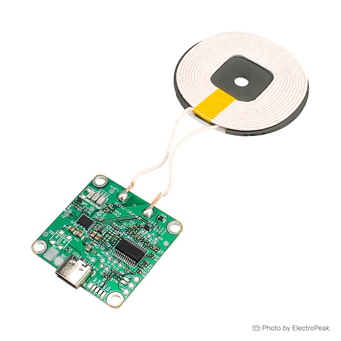
20W Qi Wireless Power Supply Transmitter Charging Coil Module
$5.7900
In stock
SKU
BAT-09-002
Volume discounts:
- +25 3 % $5.6000
- +50 5 % $5.5000
- +100 7 % $5.4000
- +300 8 % $5.3100
- +500 10 % $5.2100
Ships in 2-3 business days, then:
Free delivery in 12-15 days by Tracked Economic Shipping on orders over $100.
Free delivery in 7-10 days by Express Shipping on orders over $300.
More shipping info

Shop with confidence Learn More

20W Qi Wireless Charger Transmitter Module Review
The 20W Qi Wireless Power Supply Transmitter Charging Coil Module is a bare printed circuit board assembly with a transmitting coil for embedding wireless power into custom surfaces, desktop stands, and hardware prototypes. Unlike a boxed consumer charging pad, this component is for builders who can provide regulated direct-current power, arrange electrical insulation, handle mechanical mounting, and establish proper phone alignment.
The hardware has a practical footprint, useful physical measurements, and multi-rate automatic power negotiation up to 20W. Integration still needs careful planning: the board does not include an enclosure, documented input connector pinout, device-specific performance data, verified regulatory certifications, or stated foreign-object protection behavior. Choose a finished charger if you need a certified off-the-shelf unit or a direct automotive plug-in accessory. For custom fabrication, though, this board is a straightforward starting point among compact wireless charger modules. An identical version is also cataloged as the 20W Wireless Charger Transmitter Module for sourcing convenience.
Specifications of 20W Qi Wireless Power Supply Transmitter Charging Coil Module
- Input power supply: 5V / 9V / 12V / 13.5V, 1.5a-4a
- Coil size: 50mm * 50mm; thickness: 2.2mm
- PCBA size: 35mm * 35mm; thickness: 3.1mm
- Charging power: 5W / 7.5w/10w/15w/20w automatic identification
- Transmission distance: object (2-10mm) and space (2-14mm)
- It can separate all materials that are not metal and magnetic
- Executive standard: Qi wireless charging standard
20W Qi Transmitter Module Specifications and Integration
Designing an enclosure around this module means accounting for physical clearance and the electromagnetic needs of inductive charging. The circuit board measures 35mm by 35mm with a 3.1mm profile, while the transmitting coil has a 50mm by 50mm footprint and a 2.2mm thickness. Reserve room beyond these raw dimensions for the solder joints connecting the coil leads, incoming power wiring, and safe standoffs or nonconductive adhesive channels.
The module lists input power at 5V, 9V, 12V, or 13.5V, with current draw between 1.5A and 4A. Physical input connector details, solder pad pinouts, and quick-charge trigger behaviors are not defined on the specification sheet. Inspect the delivered board revision to identify the power terminals and confirm polarity before applying voltage. Power negotiation is automatic across 5W, 7.5W, 10W, 15W, and 20W tiers, but delivered wattage depends heavily on the target device request, available source current, thermal conditions, and spatial coupling.
| Specification | Listed Value | Why It Matters for Integration |
|---|---|---|
| PCBA Dimensions | 35mm * 35mm * 3.1mm | Determines the internal pocket size in custom stands or desk cutouts; requires extra clearance for wiring leads. |
| Coil Dimensions | 50mm * 50mm * 2.2mm | Defines the active charging surface; requires a shallow cavity beneath your nonmetallic top panel to keep the gap minimal. |
| Input Voltage & Current | 5V / 9V / 12V / 13.5V, 1.5a-4a | Demands a stable, regulated DC supply capable of at least 1.5A to 4A; polarity and connection points must be verified visually. |
| Power Identification | 5W / 7.5w/10w/15w/20w automatic | Negotiates power level automatically; higher power modes require an adequate input voltage profile and compatible receiver. |
| Transmission Distance | Object (2-10mm), space (2-14mm) | Indicates coupling depth; real-world panel thickness should remain thin (under 3 to 4mm) to maintain reliable power transfer. |
| Material Compatibility | Non-metal, non-magnetic materials | Enclosures must use wood, acrylic, ABS, or similar plastics; any metal in the magnetic field causes interference and heating. |
Projects that need a dedicated matched wireless receiver rather than mobile phone charging can use the 5V Transmitter & Receiver Coil Module, a paired transmitter and receiver set operating from a 12VDC input to deliver a regulated 5V 2A output. For custom inductive winding experiments across different wireless charging coil modules, the separately available A11 Wireless Charging Transmitting Coil 50mm/6.5uH is an option, although its electrical compatibility with this specific transmitter driver is not documented.
20W Qi Wireless Charging Coil Module Limitations
The board lists automatic identification up to 20W, but that does not guarantee 20W delivery to every phone. Many smartphones restrict third-party Qi charging to standard 5W or 7.5W profiles unless proprietary manufacturer handshakes occur. Sustained output power is also governed by thermal limits. As heat builds within an enclosed charging stand, the receiving phone or transmitter circuit will throttle current to protect internal battery chemistry.
Transmission distance is specified as 2–10mm through objects and 2–14mm through open space, but these figures represent maximum detection boundaries rather than optimal operating ranges. Single-coil transmitters are sensitive to positioning. If a phone is offset from the center of the 50mm coil by more than a few millimeters, or if an enclosure panel exceeds 3mm to 4mm in thickness, charging efficiency drops sharply. The result is often intermittent connection cycling, excessive warmth, or failure to initiate a charging session.
Safety and compatibility require evaluation before deployment:
- Smartwatch Compatibility: Although the specification notes support for Qi-enabled smartphones, smartwatches, and earbuds, many smartwatches rely on proprietary magnetic inductive systems or distinct coil geometries. Compatibility with a specific watch model cannot be assumed without empirical testing.
- Foreign-Object Detection (FOD): The listing notes advanced temperature control technology, but documented foreign-object detection thresholds, automatic cutoff behaviors, and specific protection circuits are not published. Conductive objects such as coins, keys, or RFID badges left in the magnetic field can absorb inductive energy and become hot.
- Certification Evidence: The executive standard is listed as the Qi wireless charging standard, but no published Wireless Power Consortium (WPC) registration number, CE mark, or FCC documentation is tied to this board.
- Automotive Wiring Hazards: Although 12V and 13.5V appear in the input ratings, do not splice the module directly into a vehicle's 12V electrical system without external transient voltage suppression, filtering, and regulated voltage clamping to handle load-dump spikes.
Where status reporting and verified safety indicators matter, the HW-225 5W Transmitter Module provides a conservative, documented 5W baseline with dual onboard LEDs for power state and foreign-object detection. For unmonitored installations, review documented wireless charger alternatives to avoid integration issues.
20W Qi Transmitter Module Setup and Installation
Input terminals and controller hardware can vary across manufacturing batches, so installation starts with bench verification before the module is secured in a final enclosure. No external microcontrollers, firmware, USB drivers, or software configurations are needed. The transmitter operates autonomously once direct-current power is applied.
- Inspect the Board: Examine both sides of the 35mm by 35mm circuit board. Locate the power input points, check whether the board has a physical socket, solder eyelets, or surface-mount pads, and observe any polarity silkscreen (+ and - markings).
- Connect Regulated Power: Connect a current-limited, regulated DC power source within the 5V to 13.5V range. A basic 5V test can use a Wall Power Adapter - 5V, 2A, provided you confirm the delivered board's input interface and connection polarity beforehand.
- Baseline Coupling Test: Place a known Qi-compatible phone or earbud case flat and centered directly over the 50mm coil, with no intervening case, panel, or cover. Verify that the receiving device indicates an active charging state.
- Check Thermal Behavior: Run the supervised baseline test for five to ten minutes. If the board, coil, or receiving device exhibits excessive heat buildup, or charging repeatedly connects and disconnects, remove power immediately and check input stability and coil alignment.
- Validate Enclosure Spacer: Place your intended enclosure material, such as a 2mm to 3mm sheet of acrylic or milled hardwood, between the coil and phone. Verify that the device still establishes coupling quickly and maintains a continuous charge before permanently bonding the coil into place.
Projects requiring a verified USB-C input interface with active Power Delivery protocol support should consider the IP6826 15W Transmitter Module with Type-C. It integrates an IP6826 controller, stated Qi V1.24 compliance, PD voltage negotiation, and defined Apple 7.5W and Samsung fast-charge protocol handling.
20W Qi Transmitter Module vs 15W and 5W Wireless Charger Modules
The right wireless charging module depends on available input power, enclosure space, and the protocol support required. The table below compares the verified specifications of available transmitter options.
| Feature | 20W Qi Transmitter Module | IP6826 15W Transmitter Module | HW-225 5W Transmitter Module | 5V Transmitter & Receiver Pair |
|---|---|---|---|---|
| Product Role | Transmitter PCBA + Coil | Transmitter PCBA + Coil | Transmitter PCBA + Coil | Paired Tx & Rx Modules |
| Stated Output Power | 5W / 7.5W / 10W / 15W / 20W auto | 5W / 7.5W / 10W / 15W multi-power | 5W fixed | 5V @ 2A (10W receiver output) |
| Input Voltage | 5V / 9V / 12V / 13.5V (1.5A–4A) | USB-C PD (9V / 12V for high power) | DC 5V, 1A | 12VDC input |
| Connector / Input Style | Not specified (inspect on arrival) | Type-C with PD deception | Micro-USB / solder pads | Solder terminals |
| Protocols & Standards | Qi wireless charging standard | Qi V1.24, Apple 7.5W, Samsung 10W/15W | Standard Qi inductive | Proprietary coupled inductive |
| Diagnostic Indicators | Not documented | Controller integrated | Dual LEDs (Charging & FOD) | Not documented |
| Alternative Listing | 20W Wireless Charger Module | IP6826 15W Module | HW-225 5W Module | 5V Tx & Rx Pair |
The 20W module reviewed here has the highest potential power ceiling among the bare transmitter boards, which suits custom installations where you can provide an adjustable or high-current supply. Modern USB-C-brick projects have a more defined route with the IP6826 module and its native PD negotiation. For simple low-power charging with status feedback, the HW-225 is an economical 5W option. The 5V paired system suits projects needing an isolated, point-to-point power bridge without smartphone Qi handshakes.
20W Qi Wireless Charger Transmitter Module FAQ and Buying Checklist
Frequently Asked Questions
Is this a finished wireless charger?
No. This is an open-frame transmitter PCBA and bare coil for DIY fabrication and custom hardware projects. It does not include an enclosure, rubberized pad, mounting chassis, power cable, or plug-in wall adapter.
Will my phone charge at 20W?
Not necessarily. The module negotiates 5W, 7.5W, 10W, 15W, and 20W automatically, but the actual rate is constrained by your phone's internal charging policy, thermal limits, coil alignment, and the current capability of your power supply. Most major phone brands cap standard Qi inductive charging below 20W.
What power adapter do I need for this 20W Qi transmitter module?
The module accepts 5V, 9V, 12V, or 13.5V at 1.5A to 4A. The physical connector and triggering method are not specified in the board documentation, so inspect your delivered board to determine whether it requires hardwired DC leads or a specific plug before choosing a high-current supply.
Can this Qi module connect directly to 12V or a vehicle electrical system?
No direct connection to an automotive 12V battery line is advised without intermediate conditioning. Vehicle electrical systems produce voltage spikes, load dumps, and electrical noise that can destroy unprotected power electronics. Use an intermediate regulated automotive supply.
Will it charge my smartwatch?
Verify your watch's charging technology before buying. Although the specification lists smartwatch support, popular devices from Apple, Samsung, and Garmin use specific magnetic coil alignments and proprietary inductive protocols that generally will not charge from a standard phone-sized Qi coil.
How thick can the panel, wood surface, or phone case be?
The specification states transmission through 2–10mm for objects and 2–14mm through open space. In practice, a nonmetallic spacer thickness between 2mm and 4mm provides the most reliable coupling and minimizes resistive heating.
Does this module have foreign-object detection or verified over-temperature protection?
The board advertises advanced temperature control technology, but exact thermal cutoff points, restart behaviors, and foreign-object detection circuits are not documented. For builds requiring explicit foreign-object detection indicators, the HW-225 module or the IP6826 15W Transmitter Module with Type-C provide more defined protocol implementations.
Why does wireless charging start and stop, run slowly, or get hot?
Intermittent or slow charging is almost always caused by an excessive gap between the coil and phone, off-center placement, an insufficiently rated power adapter, or thermal throttling caused by heat trapped within the enclosure.
Is this module Qi certified?
No published WPC certificate or registration ID is associated with this product number, although the board lists adherence to the Qi wireless charging standard.
For experimental setups needing alternative winding hardware, the Wireless Charging Transmitting Coil 32mm/3.7uH is sold separately, though its electrical matching with this board has not been established. More options are available across our wireless charging modules.
Purchase Decision Summary
- Ideal for: Experienced makers building embedded desktop charging spots, custom nightstands, or rapid hardware prototypes who can provide their own regulated DC power and verify physical wiring.
- Maybe for: General phone or earbud charging projects where high-speed charging is not critical and the builder is comfortable testing spacer thicknesses and alignment before permanent assembly.
- Consider another option if: You need an out-of-the-box consumer charger, verified WPC/CE compliance, guaranteed smartwatch compatibility, native USB-C Power Delivery negotiation, or direct vehicle electrical integration.
Buying Checklist
- Confirm that your receiving phone or accessory supports standard Qi inductive charging.
- Verify smartwatch charging requirements separately; do not assume standard Qi coil compatibility.
- Plan to inspect the delivered board's input pads, connector, and silkscreen polarity before powering on.
- Ensure you have a stable, regulated DC power source capable of delivering 1.5A to 4A.
- Budget physical enclosure clearance for the 35mm * 35mm board and 50mm * 50mm coil, plus wiring paths.
- Use nonmetallic, non-magnetic enclosure materials (wood, acrylic, standard plastics) over the coil area.
- Incorporate a physical ridge, recess, or graphic mark to help center the phone over the coil.
- Plan an initial supervised bench test to confirm temperature stability before sealing your enclosure.
| Interface Type | Wireless |
|---|---|
| Operating Voltage (V) | 5V / 9V / 12V / 13.5V |
| Operating Current (mA) | 1500-4000 |
| Dimensions (mm) | Coil: 50x50 mm; thickness: 2.2 mm, PCB: 35x35 mm; thickness: 3.1 mm |
| Function | wireless charger transmitter |
| Output Type | Wireless |
| Channel Count | 1 |
| Power Rating (W) | 20W |
| IP Rating | None |
| Qty | 1 |
Write Your Own Review

Please complete your information below to login.
Sign In
Create New Account