

Overview
A ps2 controller arduino setup gives you a compact handheld input device with digital buttons, pressure-sensitive inputs, analog sticks, and rumble support. If you’re building a robot, camera rig, or another remote-controlled project, most of the work is not in the code. It comes down to getting the receiver pinout right, checking voltage compatibility, and matching the wiring to the PS2X library call.
This example uses the PS2X library with the following Arduino pin mapping: CLK=13, CMD=11, ATT=10, DAT=12.
Key Takeaways
- PS2 receiver pinout and signal roles
- Safe voltage levels and level-shifting decisions
- Arduino wiring and PS2X library setup
- Reading buttons, pressure inputs, and joystick values
- Troubleshooting common PS2X controller errors
PS2 Controller Pinout
The receiver is the part you actually wire to Arduino. That matters more than the handheld controller itself, because clone receivers can differ in labeling, wire color, and electrical behavior.
The receiver interface uses an SPI-like protocol with COMMAND, DATA, CLK, and ATT as the primary signals. Signal direction is critical for correct operation:
COMMANDis host-to-controller (Arduino output).DATAis controller-to-host (Arduino input).
That means the original MOSI/MISO wording should be reversed from how it was written there.
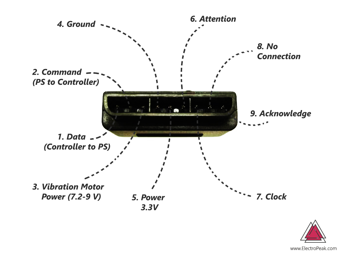
The protocol is basically SPI-like full-duplex serial communication. ATT works like chip select. CLK sets the transfer timing. DATA and COMMAND carry data in opposite directions, and ACK can be used by the controller to acknowledge received bytes.
| Pin | Signal | Direction | Function | Arduino role | Notes |
|---|---|---|---|---|---|
| 1 | DATA | Controller to host | Sends data from controller/receiver | Arduino input | Open-collector output; may require 1kΩ–10kΩ pull-up resistor |
| 2 | COMMAND | Host to controller | Sends commands to controller | Arduino output | Equivalent to host transmit line (MOSI) |
| 3 | VIBRATION | Power to motors | Supplies vibration motors | Not a normal logic signal | Requires 7.2V to 9V external supply for rumble features |
| 4 | GND | — | Ground reference | Arduino GND | Must be common ground with Arduino |
| 5 | VCC | Power input | Receiver/controller supply | 3.3V or 5V (Check datasheet) | Most clones accept 5V VCC, but logic lines are 3.3V |
| 6 | ATT | Host to controller | Attention / chip select | Arduino output | Pull low before each transfer, then high afterward |
| 7 | CLK | Host to controller | Clock | Arduino output | Normally high, SPI-like timing |
| 8 | NC | — | No connection | None | Not used |
| 9 | ACK | Controller to host | Acknowledge signal | Optional Arduino input or unused | Open-collector; some builds leave unconnected |
Warning
DATA and ACK lines often use open-collector signaling and may require pull-up resistors in the 1kΩ to 10kΩ range for reliable communication. While some builds ignore ACK, identifying it correctly during pinout verification prevents troubleshooting delays later.
Voltage Levels and Protection
Before copying any wiring diagram, verify what voltage your receiver expects and what logic levels it outputs. This is the part most likely to damage hardware if you guess.
Receiver VCC requirements vary by model; while some are rated for 3.3V, others accept 5V down to 3V. Similarly, logic levels may differ, with many receivers requiring 3.3V signals. Because specifications are not uniform across clone hardware, the safest approach is to check your exact receiver before wiring it directly.
If your receiver is a 3.3V device and your Arduino drives COMMAND, ATT, or CLK at 5V logic, level shifting is required. While some clone receivers are 5V-tolerant on the VCC pin, their logic inputs are typically 3.3V. Driving these lines with 5V signals can permanently damage the receiver.
Warning
Do not assume every PS2 receiver is 5V-safe. Most PS2 receiver logic lines operate at 3.3V. Use a logic level converter or voltage divider when connecting to a 5V Arduino to prevent hardware damage.
Practical takeaway:
| Question | What to do |
|---|---|
| Receiver VCC marked 3.3V or undocumented | Treat it as a 3.3V device until verified |
| Using a 5V Arduino | Use logic level shifting for CMD, CLK, and ATT lines |
| Receiver from a clone kit | Do not trust color coding or generic assumptions |
| Unsure about logic compatibility | Measure with a multimeter and verify before power-up |
How to Connect PS2 Controller to Arduino
The PS2X library configuration call for this setup is:
config_gamepad(13,11,10,12, true, true)
That pin order is:
CLK→ Arduino 13COMMAND→ Arduino 11ATT→ Arduino 10DATA→ Arduino 12
This matches the code, not just the drawing. If your receiver labels differ, follow the signal names rather than the wire colors.
The communication is SPI-like:
ATTgoes low to start a transactionCLKdrives the timingCOMMANDsends bytes from Arduino to the controllerDATAreturns bytes from the controllerACKcan confirm received bytes, though some builds do not use it
Warning
Before power-up, verify every receiver pin with a multimeter, do not trust wire colors, and recheck VCC and GND. Clone receivers can vary, and a swapped power connection can damage the receiver.
Before Powering Up Checklist
| Check | Why it matters |
|---|---|
| Confirm receiver pin names with a multimeter | Wire colors can vary by manufacturer |
Recheck VCC and GND | Power mistakes are the highest-risk wiring error |
| Match code pin order to real wiring | config_gamepad(clock, command, attention, data, ...) is easy to misread |
| Verify voltage compatibility | Most receivers require 3.3V logic levels; 5V signals can cause damage |
Decide whether ACK is used | Some builds leave it unconnected |
Interfacing PS2 Controller and Arduino
Once the wiring is correct, the library handles most of the protocol work. Your job is to configure the signal pins correctly, initialize the controller, and then read button and analog state in the main loop.
config_gamepad(clock, command, attention, data, Pressures?, Rumble?) So for this example, the arguments are:
clock = 13command = 11attention = 10data = 12Pressures = trueRumble = true
The controller type is detected using the readType() function.
Info
Circuit
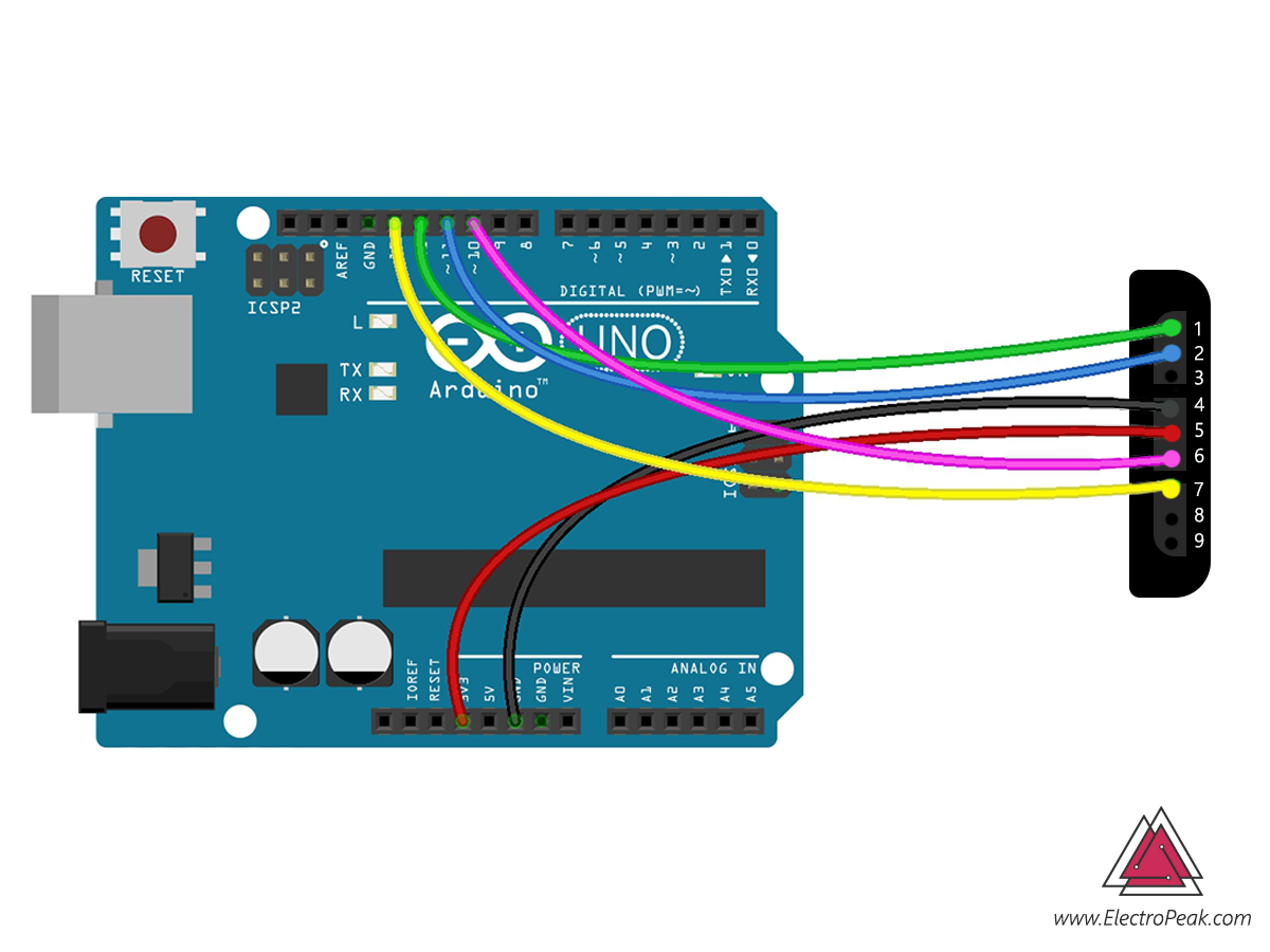
For the sample shown, the Arduino pins are:
13→CLK11→COMMAND10→ATT12→DATA

					#include <PS2X_lib.h>

PS2X ps2x;

//right now, the library does NOT support hot-pluggable controllers, meaning
//you must always either restart your Arduino after you connect the controller,
//or call config_gamepad(pins) again after connecting the controller.

int error = 0;
byte type = 0;
byte vibrate = 0;

void setup(){
 Serial.begin(57600);


 error = ps2x.config_gamepad(13,11,10,12, true, true);   //GamePad(clock, command, attention, data, Pressures?, Rumble?)

 if(error == 0){
   Serial.println("Found Controller, configured successful");
   Serial.println("Try out all the buttons, X will vibrate the controller, faster as you press harder;");
  Serial.println("holding L1 or R1 will print out the analog stick values.");
  Serial.println("Go to www.billporter.info for updates and to report bugs.");
 }

  else if(error == 1)
   Serial.println("No controller found, check wiring, see readme.txt to enable debug. visit www.billporter.info for troubleshooting tips");

  else if(error == 2)
   Serial.println("Controller found but not accepting commands. see readme.txt to enable debug. Visit www.billporter.info for troubleshooting tips");

  else if(error == 3)
   Serial.println("Controller refusing to enter Pressures mode, may not support it. ");

   type = ps2x.readType();
     switch(type) {
       case 0:
        Serial.println("Unknown Controller type");
       break;
       case 1:
        Serial.println("DualShock Controller Found");
       break;
       case 2:
         Serial.println("GuitarHero Controller Found");
       break;
     }

}

void loop(){
   /* You must Read Gamepad to get new values
   Read GamePad and set vibration values
   ps2x.read_gamepad(small motor on/off, larger motor strenght from 0-255)
   if you don't enable the rumble, use ps2x.read_gamepad(); with no values

   you should call this at least once a second
   */

 if(error == 1)
  return;

 if(type == 2){

   ps2x.read_gamepad();          //read controller

   if(ps2x.ButtonPressed(GREEN_FRET))
     Serial.println("Green Fret Pressed");
   if(ps2x.ButtonPressed(RED_FRET))
     Serial.println("Red Fret Pressed");
   if(ps2x.ButtonPressed(YELLOW_FRET))
     Serial.println("Yellow Fret Pressed");
   if(ps2x.ButtonPressed(BLUE_FRET))
     Serial.println("Blue Fret Pressed");
   if(ps2x.ButtonPressed(ORANGE_FRET))
     Serial.println("Orange Fret Pressed");


    if(ps2x.ButtonPressed(STAR_POWER))
     Serial.println("Star Power Command");

    if(ps2x.Button(UP_STRUM))          //will be TRUE as long as button is pressed
     Serial.println("Up Strum");
    if(ps2x.Button(DOWN_STRUM))
     Serial.println("DOWN Strum");


    if(ps2x.Button(PSB_START))                   //will be TRUE as long as button is pressed
         Serial.println("Start is being held");
    if(ps2x.Button(PSB_SELECT))
         Serial.println("Select is being held");


    if(ps2x.Button(ORANGE_FRET)) // print stick value IF TRUE
    {
        Serial.print("Wammy Bar Position:");
        Serial.println(ps2x.Analog(WHAMMY_BAR), DEC);
    }
 }

 else { //DualShock Controller

    ps2x.read_gamepad(false, vibrate);          //read controller and set large motor to spin at 'vibrate' speed

    if(ps2x.Button(PSB_START))                   //will be TRUE as long as button is pressed
         Serial.println("Start is being held");
    if(ps2x.Button(PSB_SELECT))
         Serial.println("Select is being held");


     if(ps2x.Button(PSB_PAD_UP)) {         //will be TRUE as long as button is pressed
       Serial.print("Up held this hard: ");
       Serial.println(ps2x.Analog(PSAB_PAD_UP), DEC);
      }
      if(ps2x.Button(PSB_PAD_RIGHT)){
       Serial.print("Right held this hard: ");
        Serial.println(ps2x.Analog(PSAB_PAD_RIGHT), DEC);
      }
      if(ps2x.Button(PSB_PAD_LEFT)){
       Serial.print("LEFT held this hard: ");
        Serial.println(ps2x.Analog(PSAB_PAD_LEFT), DEC);
      }
      if(ps2x.Button(PSB_PAD_DOWN)){
       Serial.print("DOWN held this hard: ");
     Serial.println(ps2x.Analog(PSAB_PAD_DOWN), DEC);
      }


      vibrate = ps2x.Analog(PSAB_BLUE);        //this will set the large motor vibrate speed based on
                                              //how hard you press the blue (X) button

    if (ps2x.NewButtonState())               //will be TRUE if any button changes state (on to off, or off to on)
    {
        if(ps2x.Button(PSB_L3))
         Serial.println("L3 pressed");
        if(ps2x.Button(PSB_R3))
         Serial.println("R3 pressed");
        if(ps2x.Button(PSB_L2))
         Serial.println("L2 pressed");
        if(ps2x.Button(PSB_R2))
         Serial.println("R2 pressed");
        if(ps2x.Button(PSB_GREEN))
         Serial.println("Triangle pressed");

    }


    if(ps2x.ButtonPressed(PSB_RED))             //will be TRUE if button was JUST pressed
         Serial.println("Circle just pressed");

    if(ps2x.ButtonReleased(PSB_PINK))             //will be TRUE if button was JUST released
         Serial.println("Square just released");

    if(ps2x.NewButtonState(PSB_BLUE))            //will be TRUE if button was JUST pressed OR released
         Serial.println("X just changed");


    if(ps2x.Button(PSB_L1) || ps2x.Button(PSB_R1)) // print stick values if either is TRUE
    {
        Serial.print("Stick Values:");
        Serial.print(ps2x.Analog(PSS_LY), DEC); //Left stick, Y axis. Other options: LX, RY, RX
        Serial.print(",");
        Serial.print(ps2x.Analog(PSS_LX), DEC);
        Serial.print(",");
        Serial.print(ps2x.Analog(PSS_RY), DEC);
        Serial.print(",");
        Serial.println(ps2x.Analog(PSS_RX), DEC);
    }


 }


 delay(50);

}
Reading Buttons vs Analog Sticks
The PS2X library gives you a few different ways to read input, and they are not interchangeable.
Use Button() when you want to know whether a button is currently held. Use ButtonPressed() or ButtonReleased() when you care about edges. Use Analog() when you want a pressure value or joystick position.
Joystick values typically run from 0 to 255, with the stick centered around 127 at rest. This is standard behavior for PS2 controller analog inputs in Arduino projects.
Info
Joystick values are usually centered around a mid-value, not zero. If you read around 127 at rest, that is normal behavior for many PS2 controller implementations.
| Input type | Library call | Typical values | What it means | Common use |
|---|---|---|---|---|
| Held button state | Button(...) |
0 or 1 |
Whether the button is currently pressed | Move a robot while a D-pad key is held |
| New press event | ButtonPressed(...) |
true once per press |
Detects the instant a button is pressed | Toggle a mode or trigger a sound |
| Release event | ButtonReleased(...) |
true once per release |
Detects when a button is let go | Stop an action on release |
| Pressure-sensitive button | Analog(...) on pressure input |
0 to 255 |
How hard the button is pressed | Variable speed or force |
| Analog stick axis | Analog(PSS_LX) etc. |
0 to 255 |
Stick position on one axis | Steering, speed, camera pan/tilt |
A practical mapping is easy to imagine:
- D-pad for simple movement commands
- analog sticks for proportional steering
- pressure-sensitive face buttons for variable speed
- a face button to trigger rumble or an auxiliary output
If you want a simpler analog input device for testing directional logic before using a full controller, a dual-axis joystick module with Arduino uses a much simpler interface.
PS2 Controller Layout
The physical layout matters because the library constants do not use the printed button names directly. You need to know which constant matches which control.
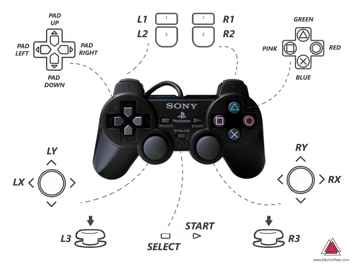
| Physical control | Library constant | Input type | Notes |
|---|---|---|---|
| Start | PSB_START |
Digital button | Used in sample code |
| Select | PSB_SELECT |
Digital button | Used in sample code |
| D-pad Up | PSB_PAD_UP |
Pressure-sensitive button | Sample reads pressure with PSAB_PAD_UP |
| D-pad Right | PSB_PAD_RIGHT |
Pressure-sensitive button | Sample reads pressure with PSAB_PAD_RIGHT |
| D-pad Left | PSB_PAD_LEFT |
Pressure-sensitive button | Sample reads pressure with PSAB_PAD_LEFT |
| D-pad Down | PSB_PAD_DOWN |
Pressure-sensitive button | Sample reads pressure with PSAB_PAD_DOWN |
| Triangle | PSB_GREEN |
Button | Printed as Triangle in sample output |
| Circle | PSB_RED |
Button | Printed as Circle in sample output |
| Square | PSB_PINK |
Button | Printed as Square in sample output |
| X | PSB_BLUE |
Button / pressure source | Sample uses pressure value for rumble |
| L1 | PSB_L1 |
Button | Used to gate stick printing |
| R1 | PSB_R1 |
Button | Used to gate stick printing |
| L2 | PSB_L2 |
Button | Used in sample code |
| R2 | PSB_R2 |
Button | Used in sample code |
| L3 | PSB_L3 |
Stick press | Used in sample code |
| R3 | PSB_R3 |
Stick press | Used in sample code |
| Left stick X | PSS_LX |
Analog axis | Printed in sample |
| Left stick Y | PSS_LY |
Analog axis | Printed in sample |
| Right stick X | PSS_RX |
Analog axis | Printed in sample |
| Right stick Y | PSS_RY |
Analog axis | Printed in sample |
PS2 Controllers Features
A PS2-style wireless controller is useful because it gives you many input types in one device: directional buttons, face buttons, shoulder buttons, stick presses, and two analog joysticks.
- 12 pressure-sensitive buttons (D-pad and face buttons)
- Digital shoulder buttons (L1, R1, L2, R2)
2analog joysticks (Left and Right)2vibration motors (Rumble)
Info
Battery count and button-count terminology can vary by controller model and clone version. Verify the exact battery tray, button behavior, and receiver labeling on the hardware you have
2.4GHz with a range of approximately 10 meters and features two internal vibration motors. Most modern wireless PS2-style controllers use 2x AAA batteries, though some models may require 3x AAA. Check the battery compartment of your specific controller for confirmation. Typical project uses include:
- wheeled robots and remote control cars
- robotic arms
- camera control
- flying robots
If your next step is a robot car, you will usually pair the controller with a motor driver such as the L298N motor driver with Arduino or a smaller driver module depending on motor current.
Troubleshooting PS2X Library Errors
Most failures come from one of three places:
- wrong pin mapping
- wrong voltage assumptions
- receiver/controller compatibility limits
Use the serial messages from the sample code as your first clue.
| Library message | Likely cause | What to check |
|---|---|---|
| No controller found | Wiring error, power issue, wrong signal mapping | Verify CLK/CMD/ATT/DAT, confirm VCC/GND, recheck receiver pinout |
| Controller found but not accepting commands | Signal direction mistake, logic-level issue, timing/compatibility problem | Confirm DATA vs COMMAND, ensure 3.3V logic levels are used, verify library pin order |
| Controller refusing to enter Pressures mode | Controller may not support pressure mode, initialization issue | Try again after reset, confirm controller type, consider disabling pressure mode if unsupported |
No controller found
Start with the basics:
- check that
ATT,CLK,COMMAND, andDATAmatch theconfig_gamepad()order - verify the receiver power pins
- do not trust wire colors
- confirm the controller is paired with its receiver
- restart after reconnecting, because hot-plugging is not supported in this example
If the receiver has clone-specific wiring, this is the most likely failure mode.
Controller found but not accepting commands
This usually points to signal-level or signal-direction problems.
The first thing to verify is that COMMAND goes from Arduino to the controller and DATA comes back from the controller. Reversing those lines can produce a setup that looks powered but never responds correctly.
Next, revisit voltage assumptions. A 3.3V receiver connected to a 5V Arduino logic bus requires level shifting to prevent communication failures and hardware damage.
Controller refusing to enter Pressures mode
Some controllers do not support pressure mode the way the library expects. The sample code handles this scenario by printing a status message and continuing execution.
If that happens:
- reset Arduino and try again
- confirm controller type with
readType() - keep in mind that clone controllers can differ
- if needed, configure the library without pressure support
Conclusion
A good arduino ps2 controller setup depends less on the library and more on careful wiring. Get the ps2 controller pinout right, verify voltage levels before applying power, then map the code exactly to CLK, COMMAND, ATT, and DATA.
Once communication is stable, the PS2X library gives you a useful mix of held-button events, pressure-sensitive inputs, joystick axes, and rumble control for robots and other remote-control builds.
Buy 2.4GHz Wireless Shock Game Controller
For the same style of receiver and controller used in this project, see the wireless PS2 game controller for Arduino and STM32.
FAQ
Do I need a logic level converter to connect a PS2 controller receiver to Arduino?
It depends on your specific hardware. ReceiverVCC specifications vary; some are rated for 3.3V, while others accept 5V down to 3V. Furthermore, many receivers require 3.3V logic signaling on their data lines. The safest approach is to verify your exact receiver first and use a logic level converter when the logic levels are not confirmed to be 5V-safe.
What is the correct PS2 controller receiver pinout for Arduino?
The receiver usually exposesDATA, COMMAND, VIBRATION, GND, VCC, ATT, CLK, NC, and ACK. For Arduino use, the critical lines are COMMAND, DATA, ATT, and CLK. COMMAND goes from Arduino to controller, while DATA comes back from the controller.
Why does the PS2X library say “No controller found” even though my wiring looks correct?
That usually means the pin mapping, power pins, or receiver identification is wrong. Do not trust wire colors on clone receivers. RecheckVCC, GND, and the config_gamepad(clock, command, attention, data) order, then reset Arduino because the example does not support hot-plugging.
What is the difference between DATA, COMMAND, ATT, CLK, and ACK on a PS2 controller?
COMMAND sends bytes from Arduino to the controller. DATA returns bytes from the controller. ATT works like chip select and starts each transaction. CLK provides timing. ACK is an acknowledge line the controller can pulse after bytes, though some Arduino builds leave it unused.
Why are my joystick values centered around 127 instead of 0?
That is normal for many PS2 controller readings. Analog stick axes are typically reported on a0 to 255 scale, so the rest position lands near the midpoint, around 127. Your code should treat that mid-value as neutral and measure movement relative to it.
Can I use pressure-sensitive PS2 buttons and rumble at the same time with Arduino?
Yes, you can use both simultaneously by callingconfig_gamepad(..., true, true). The setup can also use a pressure value from the X button to control rumble intensity. However, support can vary by controller model, so clone hardware may not behave identically.
Why doesn’t the controller work after unplugging and reconnecting it?
Because the sample setup is not hot-pluggable. The code comments explicitly say you must restart Arduino after reconnecting the controller, or call the gamepad configuration again. If you reconnect without reinitializing, the library may keep reporting errors or stale state.Can I ignore the ACK pin when using a PS2 controller with Arduino?
Sometimes yes. Many working builds do not useACK. However, you should not ignore its existence during pin identification, because it is part of the receiver pinout and can matter for compatibility or troubleshooting on some hardware. 
Comments (7)
I read your article and I have a question. How would I connect my Wired Ps2 Controller (should I follow the same wire that is linked directly to the controller) ? and is there any thing more that i needed to get other than Arduino Uno, since i am going to us it to play games on my android device Via Bluetooth?
Your project consists of the two parts. First part is connecting your wired PS2 Controller to Arduino Uno. This can be easily done following this article. Second part is connecting your Arduino Uno to your smart phone via Bluetooth. For this you need to buy a Bluetooth module since Arduino Uno doesn’t have a built-in Bluetooth module. Then by connecting the Bluetooth module to your Arduino board, you can send Controller data to your smart phone via Arduino board and Bluetooth module.
hello, i followed this tutorial to the point that my board was supposed to interface with my controller. at that point my controller never connected to the board. i checked the serial monitor for an error code and it was a jumble of symbols and didn’t put forth an error code. any recommendations?
Hi,
Make sure the baud rate of your Serial Monitor is set to the right number, which is 57600. Maybe that’s the reason you don’t see anything understandable in the Serial Monitor.
Hi, I’m pretty sure I did everything right this time, I’ve tried this with three different controllers and none of them have worked. The first one outputted all FF:0, but the second and third ones give this (I enabled debug but still couldn’t get it to work, the first controller was a knock off so maybe that was the reason for it not working.)
OUT:IN
1:0 42:0 0:0 0:0 0:0 0:0 0:0 0:0 0:0 0:0 0:0 0:0 0:0 0:0 0:0 0:0 0:0 0:0 0:0 0:0 0:0
OUT:IN
1:0 42:0 0:0 0:0 0:0 0:0 0:0 0:0 0:0 0:0 0:0 0:0 0:0 0:0 0:0 0:0 0:0 0:0 0:0 0:0 0:0
Controller mode not matched or no controller found
Expected 0x41 or 0x73, got 0
No controller found, check wiring, see readme.txt to enable debug. visit http://www.billporter.info for troubleshooting tips
Unknown Controller type
I’ve got my guitar hero ps2 controller wired to my arduino using the library. I’m using jumper wires from the pins on the end of the guitar hero controller to connect it to the Arduino. The arduino says it doesn’t see any controller connected.
Hi Noah,
Check out this article it might help you.