MPU9250 9-Axis Gyro Accelerator Magnetometer Module Features
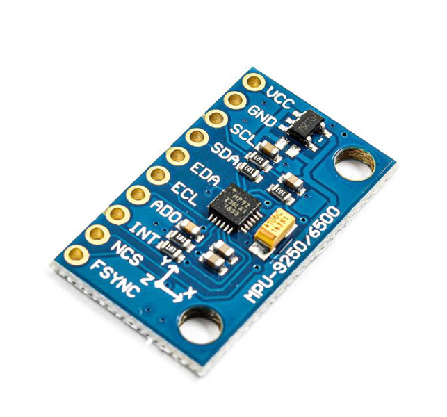
The MPU9250 9-Axis Gyro Accelerator Magnetometer Module can provide acceleration, angle change and magnetic field on 3 axes x, y and z with high speed and accuracy. This module also features an embedded temperature sensor that can measure the temperature range between -40 to +85 degrees Celsius. The communication protocol of this module is I2C.
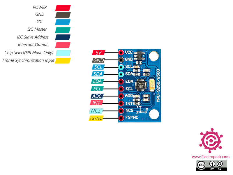
MPU9250 9-Axis Gyro Accelerator Magnetometer Module Pinout
This Module has 10 pins:
- VCC: Module power supply – 5V
- GND: Ground
- SCL: I2C Serial clock
- SDA: I2C Serial Data
- EDA: I2C Master Serial Data to communicate with sensor or other modules
- ECL: I2C Master Serial Clock to communicate with sensor or other modules
- AD0: I2C address select pin (If this pin is LOW, the I2C address of the module will be 0x68. Otherwise, if the pin is HIGH, the address will be 0x69)
- INT: Interrupt digital output
- NCS: Chip select (SPI mode only)
- FSYNC: Frame Synchronization Digital Input (changing I2C bus speed)
You can see the pinout of this module in the image below.
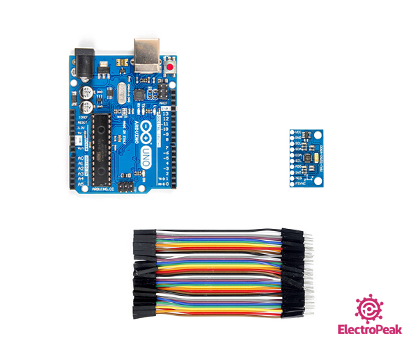
Required Material
Hardware component
Software Apps
Interfacing MPU9250 9-Axis Gyro Accelerator Magnetometer Module with Arduino
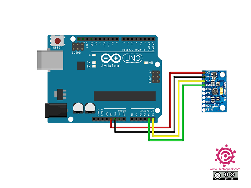
Step 1: Circuit
The following circuit show how you should connect Arduino to MPU9250 module. Connect wires accordingly.
Step 2: Library
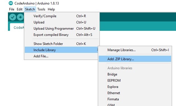
Download the MPU9250 library here. Then go to Include Library and install it.
Step 3: Code
Upload the following code to your Arduino. Then open the Serial Monitor.
 /*
Basic_I2C.ino
Brian R Taylor
[email protected]

Copyright (c) 2017 Bolder Flight Systems

Permission is hereby granted, free of charge, to any person obtaining a copy of this software
and associated documentation files (the "Software"), to deal in the Software without restriction,
including without limitation the rights to use, copy, modify, merge, publish, distribute,
sublicense, and/or sell copies of the Software, and to permit persons to whom the Software is
furnished to do so, subject to the following conditions:

The above copyright notice and this permission notice shall be included in all copies or
substantial portions of the Software.

THE SOFTWARE IS PROVIDED "AS IS", WITHOUT WARRANTY OF ANY KIND, EXPRESS OR IMPLIED, INCLUDING
BUT NOT LIMITED TO THE WARRANTIES OF MERCHANTABILITY, FITNESS FOR A PARTICULAR PURPOSE AND
NONINFRINGEMENT. IN NO EVENT SHALL THE AUTHORS OR COPYRIGHT HOLDERS BE LIABLE FOR ANY CLAIM,
DAMAGES OR OTHER LIABILITY, WHETHER IN AN ACTION OF CONTRACT, TORT OR OTHERWISE, ARISING FROM,
OUT OF OR IN CONNECTION WITH THE SOFTWARE OR THE USE OR OTHER DEALINGS IN THE SOFTWARE.
*/

#include "MPU9250.h"

// an MPU9250 object with the MPU-9250 sensor on I2C bus 0 with address 0x68
MPU9250 IMU(Wire,0x68);
int status;

void setup() {
  // serial to display data
  Serial.begin(115200);
  while(!Serial) {}

  // start communication with IMU
  status = IMU.begin();
  if (status < 0) {
    Serial.println("IMU initialization unsuccessful");
    Serial.println("Check IMU wiring or try cycling power");
    Serial.print("Status: ");
    Serial.println(status);
    while(1) {}
  }
}

void loop() {
  // read the sensor
  IMU.readSensor();
  // display the data
  Serial.print(IMU.getAccelX_mss(),6);
  Serial.print("\t");
  Serial.print(IMU.getAccelY_mss(),6);
  Serial.print("\t");
  Serial.print(IMU.getAccelZ_mss(),6);
  Serial.print("\t");
  Serial.print(IMU.getGyroX_rads(),6);
  Serial.print("\t");
  Serial.print(IMU.getGyroY_rads(),6);
  Serial.print("\t");
  Serial.print(IMU.getGyroZ_rads(),6);
  Serial.print("\t");
  Serial.print(IMU.getMagX_uT(),6);
  Serial.print("\t");
  Serial.print(IMU.getMagY_uT(),6);
  Serial.print("\t");
  Serial.print(IMU.getMagZ_uT(),6);
  Serial.print("\t");
  Serial.println(IMU.getTemperature_C(),6);
  delay(100);
}
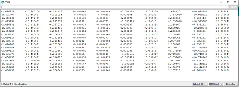
The above code, which is an example of Arduino, shows the angle change, momentary acceleration and magnetic field on three axes and also the temperature.
The result is as follows.

