

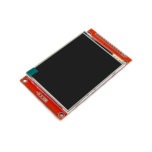
2.8 INCH TFT LCD Display Features
The TFT display is a kind of LCD that is connected to each pixel using a transistor and it features low current consumption, high-quality, high-resolution and backlight. This 2.8-inch full color LCD has a narrow PCB display. The resolution is 320×280 pixels and it has a four-wire SPI interface and white backlight.
This display also has a touch screen and SD card slot.
Note
The module voltage is 3.3V and voltage divider is required to interface it with Arduino.
To download datasheet and for more details, refer to link below.
http://www.lcdwiki.com/2.8inch_SPI_Module_ILI9341_SKU:MSP2807
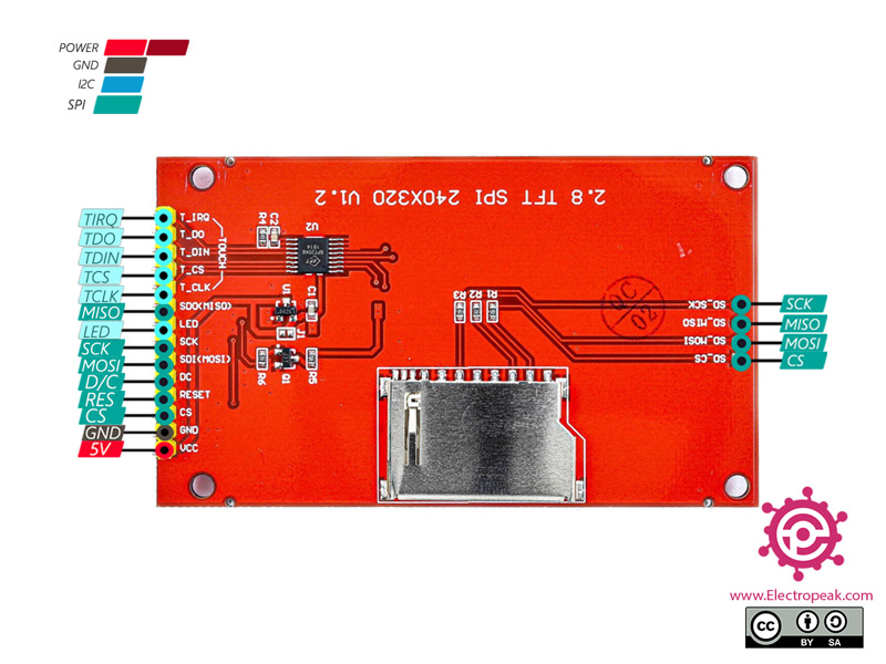
2.8 INCH TFT LCD Display Pinout
This module comprises 20 pins, each serving a specific purpose. Here is a breakdown of the essential pins:
- VIN: Module power supply – 3.3-5 V
- GND: Ground
- RST: LCD reset
- CS: LCD chip select signal, low level enable
- D/C: Data selection signal
- MOSI: SPI bus write data signal
- SCK: SPI bus clock signal
- LED: Backlight control
- T_CLK: Touch SPI bus clock signal
- T_CS: Touch screen chip select signal, low level enable
- T_DIN: Touch SPI bus input
- T_DO: Touch SPI bus input
- T_IRQ: Touch screen interrupt signal, low level when touch is detected
- SD-MOSI: SPI bus write data signal
- SD-MISO: SPI bus read data signal, if you do not need to the read function, you can not connect it
- SD-SCK: SPI bus clock signal
- SD-CS: Chip select signal for SPI protocol (SD Card)
You can see the pinout of this module in the image below.
Required Materials
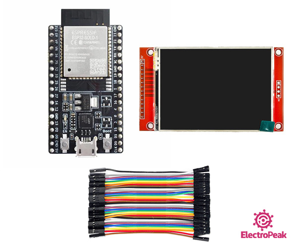
Hardware Components
Software Apps
Interfacing 2.8 INCH TFT LCD Display with ESP32
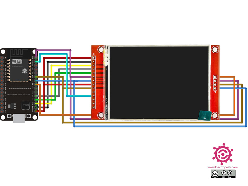
Step 1: Circuit
The following circuit diagram shows how you should connect ESP32 to this Display. Connect wires accordingly.
Step 2: Library
To ensure seamless compatibility, install the TFT_eSPI library in the Arduino IDE using the following link:
https://github.com/Bodmer/TFT_eSPI
After that, go to the address of installed library and open the User_Setup.h file and refer to line
EDIT THE PIN NUMBERS IN THE LINES FOLLOWING TO SUIT YOUR ESP32 SETUP
and uncomment the following lines and comment on the lines which are uncommented.
#define TFT_MISO 19
#define TFT_MOSI 23
#define TFT_SCLK 18
#define TFT_CS 15 // Chip select control pin
#define TFT_DC 2 // Data Command control pin
#define TFT_RST 4 // Reset pin (could connect to RST pin)
You can also download the ready file from here, unzip it and use in your project.
Step 3: Code
Upload the following code to your ESP32 microcontroller.
    /*
  Example animated analogue meters using a ILI9341 TFT LCD screen

  Needs Font 2 (also Font 4 if using large scale label)

  Make sure all the display driver and pin comnenctions are correct by
  editting the User_Setup.h file in the TFT_eSPI library folder.

  #########################################################################
  ###### DON'T FORGET TO UPDATE THE User_Setup.h FILE IN THE LIBRARY ######
  #########################################################################
*/

#include <TFT_eSPI.h> // Hardware-specific library
#include <SPI.h>

TFT_eSPI tft = TFT_eSPI();       // Invoke custom library

#define TFT_GREY 0x5AEB

#define LOOP_PERIOD 35 // Display updates every 35 ms

float ltx = 0;    // Saved x coord of bottom of needle
uint16_t osx = 120, osy = 120; // Saved x & y coords
uint32_t updateTime = 0;       // time for next update

int old_analog =  -999; // Value last displayed
int old_digital = -999; // Value last displayed

int value[6] = {0, 0, 0, 0, 0, 0};
int old_value[6] = { -1, -1, -1, -1, -1, -1};
int d = 0;

void setup(void) {
  tft.init();
  tft.setRotation(0);
  Serial.begin(57600); // For debug
  tft.fillScreen(TFT_BLACK);

  analogMeter(); // Draw analogue meter

  // Draw 6 linear meters
  byte d = 40;
  plotLinear("A0", 0, 160);
  plotLinear("A1", 1 * d, 160);
  plotLinear("A2", 2 * d, 160);
  plotLinear("A3", 3 * d, 160);
  plotLinear("A4", 4 * d, 160);
  plotLinear("A5", 5 * d, 160);

  updateTime = millis(); // Next update time
}


void loop() {
  if (updateTime <= millis()) {
    updateTime = millis() + LOOP_PERIOD;

    d += 4; if (d >= 360) d = 0;

    //value[0] = map(analogRead(A0), 0, 1023, 0, 100); // Test with value form Analogue 0

    // Create a Sine wave for testing
    value[0] = 50 + 50 * sin((d + 0) * 0.0174532925);
    value[1] = 50 + 50 * sin((d + 60) * 0.0174532925);
    value[2] = 50 + 50 * sin((d + 120) * 0.0174532925);
    value[3] = 50 + 50 * sin((d + 180) * 0.0174532925);
    value[4] = 50 + 50 * sin((d + 240) * 0.0174532925);
    value[5] = 50 + 50 * sin((d + 300) * 0.0174532925);

    //unsigned long t = millis();

    plotPointer();

    plotNeedle(value[0], 0);

    //Serial.println(millis()-t); // Print time taken for meter update
  }
}


// #########################################################################
//  Draw the analogue meter on the screen
// #########################################################################
void analogMeter()
{
  // Meter outline
  tft.fillRect(0, 0, 239, 126, TFT_GREY);
  tft.fillRect(5, 3, 230, 119, TFT_WHITE);

  tft.setTextColor(TFT_BLACK);  // Text colour

  // Draw ticks every 5 degrees from -50 to +50 degrees (100 deg. FSD swing)
  for (int i = -50; i < 51; i += 5) {
    // Long scale tick length
    int tl = 15;

    // Coodinates of tick to draw
    float sx = cos((i - 90) * 0.0174532925);
    float sy = sin((i - 90) * 0.0174532925);
    uint16_t x0 = sx * (100 + tl) + 120;
    uint16_t y0 = sy * (100 + tl) + 140;
    uint16_t x1 = sx * 100 + 120;
    uint16_t y1 = sy * 100 + 140;

    // Coordinates of next tick for zone fill
    float sx2 = cos((i + 5 - 90) * 0.0174532925);
    float sy2 = sin((i + 5 - 90) * 0.0174532925);
    int x2 = sx2 * (100 + tl) + 120;
    int y2 = sy2 * (100 + tl) + 140;
    int x3 = sx2 * 100 + 120;
    int y3 = sy2 * 100 + 140;

    // Yellow zone limits
    //if (i >= -50 && i < 0) {
    //  tft.fillTriangle(x0, y0, x1, y1, x2, y2, TFT_YELLOW);
    //  tft.fillTriangle(x1, y1, x2, y2, x3, y3, TFT_YELLOW);
    //}

    // Green zone limits
    if (i >= 0 && i < 25) {
      tft.fillTriangle(x0, y0, x1, y1, x2, y2, TFT_GREEN);
      tft.fillTriangle(x1, y1, x2, y2, x3, y3, TFT_GREEN);
    }

    // Orange zone limits
    if (i >= 25 && i < 50) {
      tft.fillTriangle(x0, y0, x1, y1, x2, y2, TFT_ORANGE);
      tft.fillTriangle(x1, y1, x2, y2, x3, y3, TFT_ORANGE);
    }

    // Short scale tick length
    if (i % 25 != 0) tl = 8;

    // Recalculate coords incase tick lenght changed
    x0 = sx * (100 + tl) + 120;
    y0 = sy * (100 + tl) + 140;
    x1 = sx * 100 + 120;
    y1 = sy * 100 + 140;

    // Draw tick
    tft.drawLine(x0, y0, x1, y1, TFT_BLACK);

    // Check if labels should be drawn, with position tweaks
    if (i % 25 == 0) {
      // Calculate label positions
      x0 = sx * (100 + tl + 10) + 120;
      y0 = sy * (100 + tl + 10) + 140;
      switch (i / 25) {
        case -2: tft.drawCentreString("0", x0, y0 - 12, 2); break;
        case -1: tft.drawCentreString("25", x0, y0 - 9, 2); break;
        case 0: tft.drawCentreString("50", x0, y0 - 6, 2); break;
        case 1: tft.drawCentreString("75", x0, y0 - 9, 2); break;
        case 2: tft.drawCentreString("100", x0, y0 - 12, 2); break;
      }
    }

    // Now draw the arc of the scale
    sx = cos((i + 5 - 90) * 0.0174532925);
    sy = sin((i + 5 - 90) * 0.0174532925);
    x0 = sx * 100 + 120;
    y0 = sy * 100 + 140;
    // Draw scale arc, don't draw the last part
    if (i < 50) tft.drawLine(x0, y0, x1, y1, TFT_BLACK);
  }

  tft.drawString("%RH", 5 + 230 - 40, 119 - 20, 2); // Units at bottom right
  tft.drawCentreString("%RH", 120, 70, 4); // Comment out to avoid font 4
  tft.drawRect(5, 3, 230, 119, TFT_BLACK); // Draw bezel line

  plotNeedle(0, 0); // Put meter needle at 0
}

// #########################################################################
// Update needle position
// This function is blocking while needle moves, time depends on ms_delay
// 10ms minimises needle flicker if text is drawn within needle sweep area
// Smaller values OK if text not in sweep area, zero for instant movement but
// does not look realistic... (note: 100 increments for full scale deflection)
// #########################################################################
void plotNeedle(int value, byte ms_delay)
{
  tft.setTextColor(TFT_BLACK, TFT_WHITE);
  char buf[8]; dtostrf(value, 4, 0, buf);
  tft.drawRightString(buf, 40, 119 - 20, 2);

  if (value < -10) value = -10; // Limit value to emulate needle end stops
  if (value > 110) value = 110;

  // Move the needle util new value reached
  while (!(value == old_analog)) {
    if (old_analog < value) old_analog++;
    else old_analog--;

    if (ms_delay == 0) old_analog = value; // Update immediately id delay is 0

    float sdeg = map(old_analog, -10, 110, -150, -30); // Map value to angle
    // Calcualte tip of needle coords
    float sx = cos(sdeg * 0.0174532925);
    float sy = sin(sdeg * 0.0174532925);

    // Calculate x delta of needle start (does not start at pivot point)
    float tx = tan((sdeg + 90) * 0.0174532925);

    // Erase old needle image
    tft.drawLine(120 + 20 * ltx - 1, 140 - 20, osx - 1, osy, TFT_WHITE);
    tft.drawLine(120 + 20 * ltx, 140 - 20, osx, osy, TFT_WHITE);
    tft.drawLine(120 + 20 * ltx + 1, 140 - 20, osx + 1, osy, TFT_WHITE);

    // Re-plot text under needle
    tft.setTextColor(TFT_BLACK);
    tft.drawCentreString("%RH", 120, 70, 4); // // Comment out to avoid font 4

    // Store new needle end coords for next erase
    ltx = tx;
    osx = sx * 98 + 120;
    osy = sy * 98 + 140;

    // Draw the needle in the new postion, magenta makes needle a bit bolder
    // draws 3 lines to thicken needle
    tft.drawLine(120 + 20 * ltx - 1, 140 - 20, osx - 1, osy, TFT_RED);
    tft.drawLine(120 + 20 * ltx, 140 - 20, osx, osy, TFT_MAGENTA);
    tft.drawLine(120 + 20 * ltx + 1, 140 - 20, osx + 1, osy, TFT_RED);

    // Slow needle down slightly as it approaches new postion
    if (abs(old_analog - value) < 10) ms_delay += ms_delay / 5;

    // Wait before next update
    delay(ms_delay);
  }
}

// #########################################################################
//  Draw a linear meter on the screen
// #########################################################################
void plotLinear(char *label, int x, int y)
{
  int w = 36;
  tft.drawRect(x, y, w, 155, TFT_GREY);
  tft.fillRect(x + 2, y + 19, w - 3, 155 - 38, TFT_WHITE);
  tft.setTextColor(TFT_CYAN, TFT_BLACK);
  tft.drawCentreString(label, x + w / 2, y + 2, 2);

  for (int i = 0; i < 110; i += 10)
  {
    tft.drawFastHLine(x + 20, y + 27 + i, 6, TFT_BLACK);
  }

  for (int i = 0; i < 110; i += 50)
  {
    tft.drawFastHLine(x + 20, y + 27 + i, 9, TFT_BLACK);
  }

  tft.fillTriangle(x + 3, y + 127, x + 3 + 16, y + 127, x + 3, y + 127 - 5, TFT_RED);
  tft.fillTriangle(x + 3, y + 127, x + 3 + 16, y + 127, x + 3, y + 127 + 5, TFT_RED);

  tft.drawCentreString("---", x + w / 2, y + 155 - 18, 2);
}

// #########################################################################
//  Adjust 6 linear meter pointer positions
// #########################################################################
void plotPointer(void)
{
  int dy = 187;
  byte pw = 16;

  tft.setTextColor(TFT_GREEN, TFT_BLACK);

  // Move the 6 pointers one pixel towards new value
  for (int i = 0; i < 6; i++)
  {
    char buf[8]; dtostrf(value[i], 4, 0, buf);
    tft.drawRightString(buf, i * 40 + 36 - 5, 187 - 27 + 155 - 18, 2);

    int dx = 3 + 40 * i;
    if (value[i] < 0) value[i] = 0; // Limit value to emulate needle end stops
    if (value[i] > 100) value[i] = 100;

    while (!(value[i] == old_value[i])) {
      dy = 187 + 100 - old_value[i];
      if (old_value[i] > value[i])
      {
        tft.drawLine(dx, dy - 5, dx + pw, dy, TFT_WHITE);
        old_value[i]--;
        tft.drawLine(dx, dy + 6, dx + pw, dy + 1, TFT_RED);
      }
      else
      {
        tft.drawLine(dx, dy + 5, dx + pw, dy, TFT_WHITE);
        old_value[i]++;
        tft.drawLine(dx, dy - 6, dx + pw, dy - 1, TFT_RED);
      }
    }
  }
}
This code serves as a test script, showcasing various graphical shapes and designs on the display. Verify the successful integration of the display by observing the displayed visuals.
Get ready to explore the possibilities of the 2.8 Inch TFT LCD display with touch screen capability and unleash your creativity in your ESP32 projects.

Comments (21)
Mohammad: This is an impressive posting! I have been looking for this type of post in order to interface my DOIT ESP32 DEVKIT V1 to my 2.8-inch SPI TFT MSP2807 Display. I have made a successful interface between my Arduino UNO Rev 3 Module and the MSP2807 Display. However, I wish to move away from using 10 pairs of series connected step down voltage divider resistors.
I need some help from you to configure my user setup file for my application. I am using the MSP2807 Display with the ILI9341 Driver, driven by the DOIT ESP32 DEVKIT V1. I have placed the DOIT ESP32 DEVKIT V1 Board File into my IDE Board List.
Please help me to configure my attached User File to make this happen. I would like to e-mail the following documents to you:
1. A PDF showing a close up drawing for the DOIT ESP32 DEVKIT V1 with all of its pin outs identified
2. A PDF showing the connection between this ESP32 Module and the MSP2807, taken from this posting; a larger drawing of the ESP32 Module by itself; and a table summarizing the interconnections shown in your connection drawing at the top of this figure .
3. A copy of your “Animated Analog Meter” sketch with the User Setup File pasted on top of the sketch.
How can I send these items to you?
please explain, dumbass. how do you connect 3 pins from the required materials with one wire? fucking copy-paste
please let me know dirty john. do you have any expereince with SPI interface?
Thanks for the post. It worked for me right away. Saved me a lot of time.
This worked on the the first go around. That never happens with me. LOL
Thanks for the excellent presentation and fine business graphic demo display.
Very Nice!
you got it my friend
Hi,
Do ou have done any touch function testing?
Thanks
summer
I have set up as per your diagram except for the touch, but all I get is a blank white screen, I wonder how it worked for some folks, Any suggestions?
Hi Richard
It mostly comes down to wiring.
Double-check your wiring as well as the config file
Hello, I’ve coded a tft 2.8 touchscreen LCD with an Arduino uno; using the
SPI and #include
#include
#include ,
libraries to code it
I recently learnt about the esp23, and i was wondering if it will work if i just transfer the wiring to it
Hello
Can you send just the library name? In your message, after “include,” there’s nothing.
Also, if you’re referring to the MCUfriend or Adafruit library, I recommend using TFT_eSPI for ESP to achieve better results.
The two libraries for Arduino often don’t function properly with ESP, or they might lead to issues.
Hi sir, I made connection by your circuit diagram and I only get white screen sir .
Do I get you WhatsApp numbers for clarification of doubt sir
Hi, have you configured the “User_Setup.h” file in the library directory?
The library directory is usually located in %UserProfile%\Documents\Arduino\libraries
Hi,sir
I have configured correctly sir.but I did mistake is wiring after I made wiring perfectly and made user setup file correctly then I got the display sir thank you so much for your guidance. Sir
Sir now I have problem to make touch. I used Adafruit_FT6206 library on my final year project entirely on simulation
(WOKWI SIMULATOR) . But in real time I cannot configure this library to my project .sir
You’re welcome!
The touch driver for this LCD is the XPT2046. For configuring the touch functionality of this display, it’s best to refer to these links. link1 , link2
Thank you sir , the display working perfectly. I get the proper touching coordinates and mapping. ???????
You’re Welcome
Hello, I am stuck with a white screen. i am using waveshare esp32-s3-nano https://www.waveshare.com/esp32-s3-nano.htm. and i changed the pin configuration in the set up as the micro controller doesnt hace the designated GPIO numbers in the regualr setup. and no matter how i change it i cannot get the screen to display anything but a white screen. please help!
Hello! you’re using the ESP32S3 board, please update the TFT_eSPI library to the latest version. Then, in the library file ‘User_Setup_Select’, comment out the line ‘#include <User_Setup.h>’ and uncomment the line ‘#include <User_Setups/Setup70b_ESP32_S3_ILI9341.h>’. Next, open the ‘Setup70b_ESP32_S3_ILI9341’ file and configure the pinout according to your setup. Keep in mind that the pins for TFT_MOSI, TFT_SCLK, and TFT_MISO should remain as 11, 12, and 13 respectively. You can modify the other pins as needed.
hello sir..
i am using waveshare ESP32 S3 board, how to connect this ESP32 with 2.8 TFT SPI Display. kindly give me the solution. Thanks in advance
Hello Arun,
This code also works with the ESP32-S3. To set it up:
1. Go to the file “User_Setup_Select.h”.
2. Uncomment this line:
#include <User_Setups/Setup70b_ESP32_S3_ILI9341.h>3. Comment this line:
#include <User_Setup.h>4. Then, open the file “User_Setups/Setup70b_ESP32_S3_ILI9341.h” and connect the pins as specified in that file.
The file “User_Setup.h” is no longer required for this setup.