
Introduction
You must have come across the terms “square pulse generation” and “pulse width modulation” (or PWM), and you probably have worked with them—for example, which pins of Arduino (or any other microcontroller) can generate PWM pulses. Pulse width modulation is a technique for generating square pulse signals with desired features, which are widely used in different areas of Electronics. Some of these applications include controlling the color and brightness of LEDs, controlling engines and timers, and synchronizing digital systems. This technique is also used in almost all switching power supplies and other methods for controlling the voltage or power.
Due to the importance of this concept, first, we will briefly explain it.
What is PWM?
PWM (or Pulse Width Modulation) is a process through which we control and adjust the parameters of a square waveform. The most important parameters include frequency, duty cycle, and voltage amplitude.
Consider the figure below:
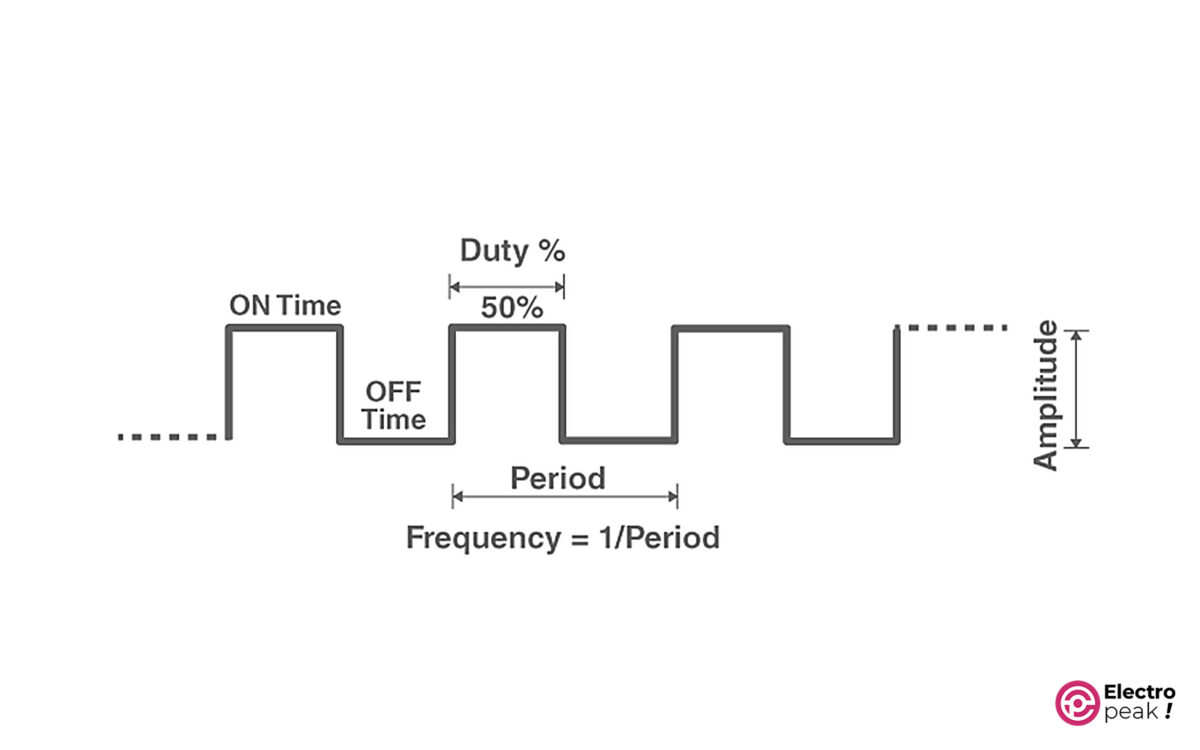
Here are the main parameters of a square waveform:
Period: The time taken for one cycle of the waveform. Its symbol is T, with a unit of “second.”
Frequency: The inverse of period. In other words, frequency is the number of periods per second. Its symbol is “f,” with a unit of Hz (1Hz=1/1s).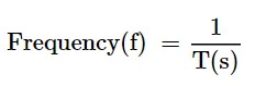
Duty Cycle: The ratio of on-time to the period. And it is usually represented in a percentage. 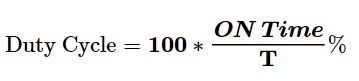
Amplitude: voltage amplitude.
Example: We have a voltage waveform that is on for 1.2 seconds and off for 0.8 seconds. And this process is repeated every 2 seconds. Find the frequency and duty cycle of the waveform.
Simple, isn’t it? Since the process is repeated every 2 seconds, the period would be 2 seconds.
Frequency = 1/2 = 0.5 Hz.
Duty Cycle: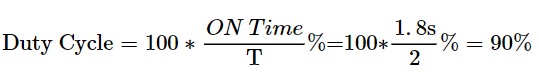
In this tutorial, we will not provide a complete explanation of the PWM concept and the related methods and applications. Therefore, the introduction above is necessary and perhaps enough for our purposes. You can refer to the numerous articles about this topic if you need more information.
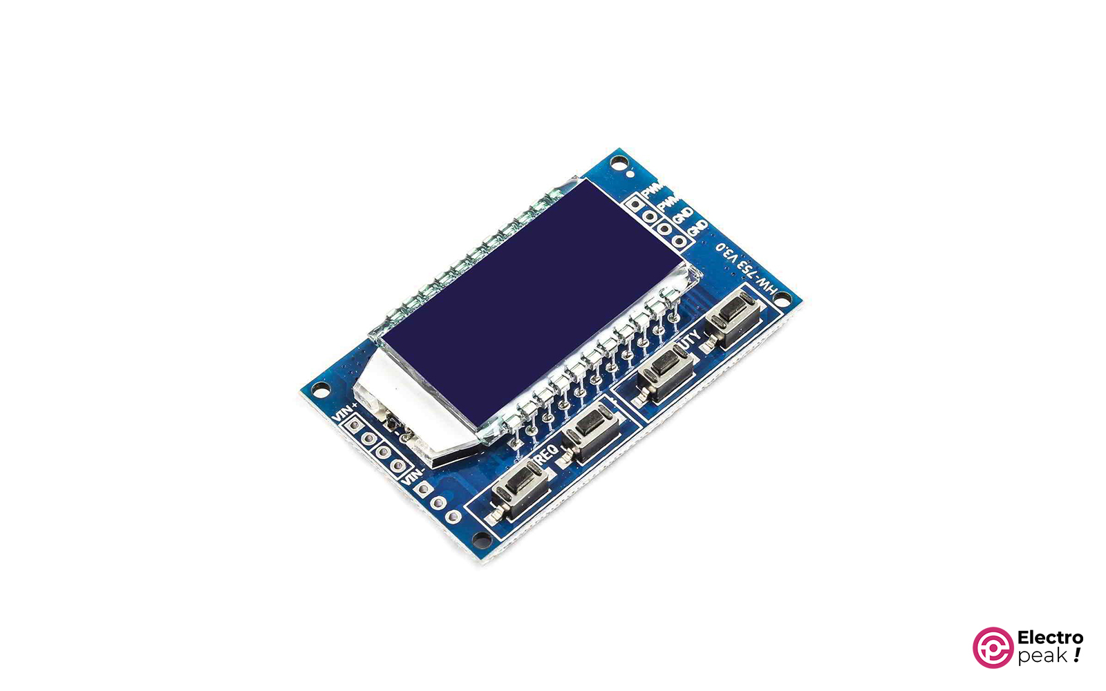
Various modules and components have been designed and manufactured to generate PWM signals with different methods. In this tutorial, we will learn how to use the XY-LPWM module, which is almost a complete and well-equipped component for our purpose.
XY-LPWM PWM Signal Generator Module Features
XY-LPWM is a square pulse generator module that has more features compared to many other modules in this family. The output frequency of the module ranges from 0 Hz to 150 KHz, and you can adjust the duty cycle from 0 to 100%. In addition, the accuracy of the output frequency is 2% which is considered a great accuracy for many applications.
It is very easy to work with the XY-LPWM module due to the one LCD and four push buttons to adjust the frequency and duty cycle independently. In addition, the TTL serial user interface is designed on the module, by which we can communicate with the module through the serial port of a computer.
The input voltage is between 3.3 to 30 DC volts. The voltage amplitude of the output pulse is also generated without any drop compared to the input voltage amplitude.
XY-LPWM Specifications
• Input voltage: 3.3 to 30 volts
• Current consumption of module: 20mA (at 5V power supply)
• Output voltage amplitude: equals to the input voltage amplitude
• Frequency: 0 Hz to 150 KHz
• Frequency Accuracy: around 2%
• Duty cycle: 0 to 100%
• Maximum output current: 30 mA
• Operating temperature: -20 to 70 °C
• An LCD screen to display the frequency and duty cycle of the generated wave
• TTL Serial Interface with a 3.3V logic level
• Dimensions: 52*32*10 mm
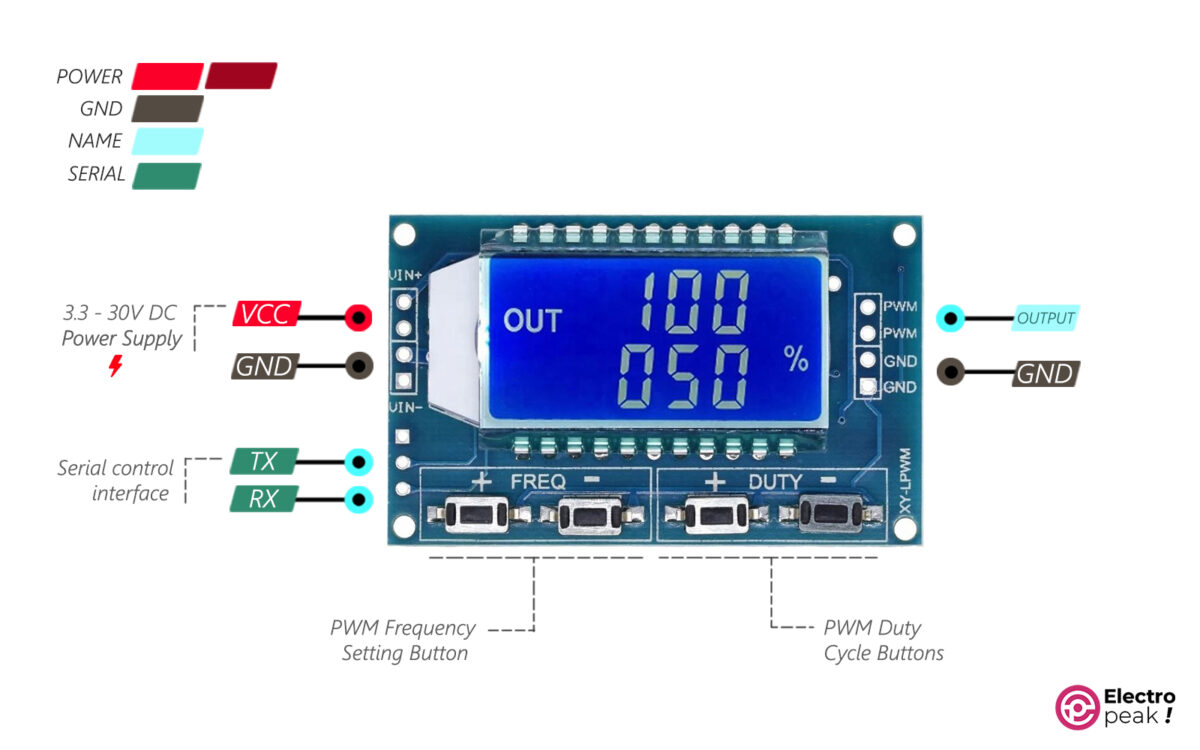
XY-LPWM Pinout
• VIN+: power supply of module (input voltage)
• GND: ground
• VIN-: ground
• PWM: output pin of pulse
Serial communication pins:
• TXD: transmit data pin
• RXD: receive data pin
Required Materials

Hardware Components
*: We use PWM Switch Module to increase the module’s output power. And there are many similar items for it in the market. Of course, you don’t need to buy this module if you are looking for a low-power output.
**: The 12V fan also tests and simulates the engine speed control. You don’t need this component for other purposes.
How to Use XY-LPWM Digital Pulse Generator Module
Module's Power Supply
You should use this module within a voltage range of 3 to 30 volts which are supplied by the VIN+ pins. The two VIN+ pins are internally connected, so all you have to do is connect one to the power supply’s positive pin. The same applies to the VIN- pins connected to the circuit GND.
The power input of the module is protected by a Schottky diode against high voltages. In addition, the logic circuit of the module works with a voltage level of 3.3 which is provided by a 3.3V regulator on the board.
When the output voltage goes below 4V, the screen backlight decreases. The module, however, functions properly even at voltages as low as 3V.
The module draws 20mA from the power supply at operating voltages lower than or equal to 5V. In other words, the power consumption at an operating voltage of 5V is about 0.1 w.
For example, at an operating voltage of 5V, the maximum total power consumption is equal to the sum of the following powers:
Module's power consumption= operating voltage * module's current consumption= 20mA * 5V = 0.1 w,
Output power = output voltage * output current = 30mA * 5V = 0.15 w.
The power supply, therefore, must provide at least 0.25 w of power, i.e. it must provide at least 50mA at an operating voltage of 5V.
Initial Test of XY-LPWM PWM Signal Generator Module
For a simple test on XY-LPWM module, connect the wires as shown below. The power supply voltage must be between 3.3 to 30 volts.
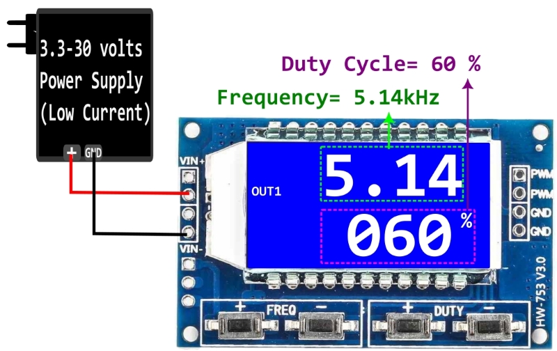
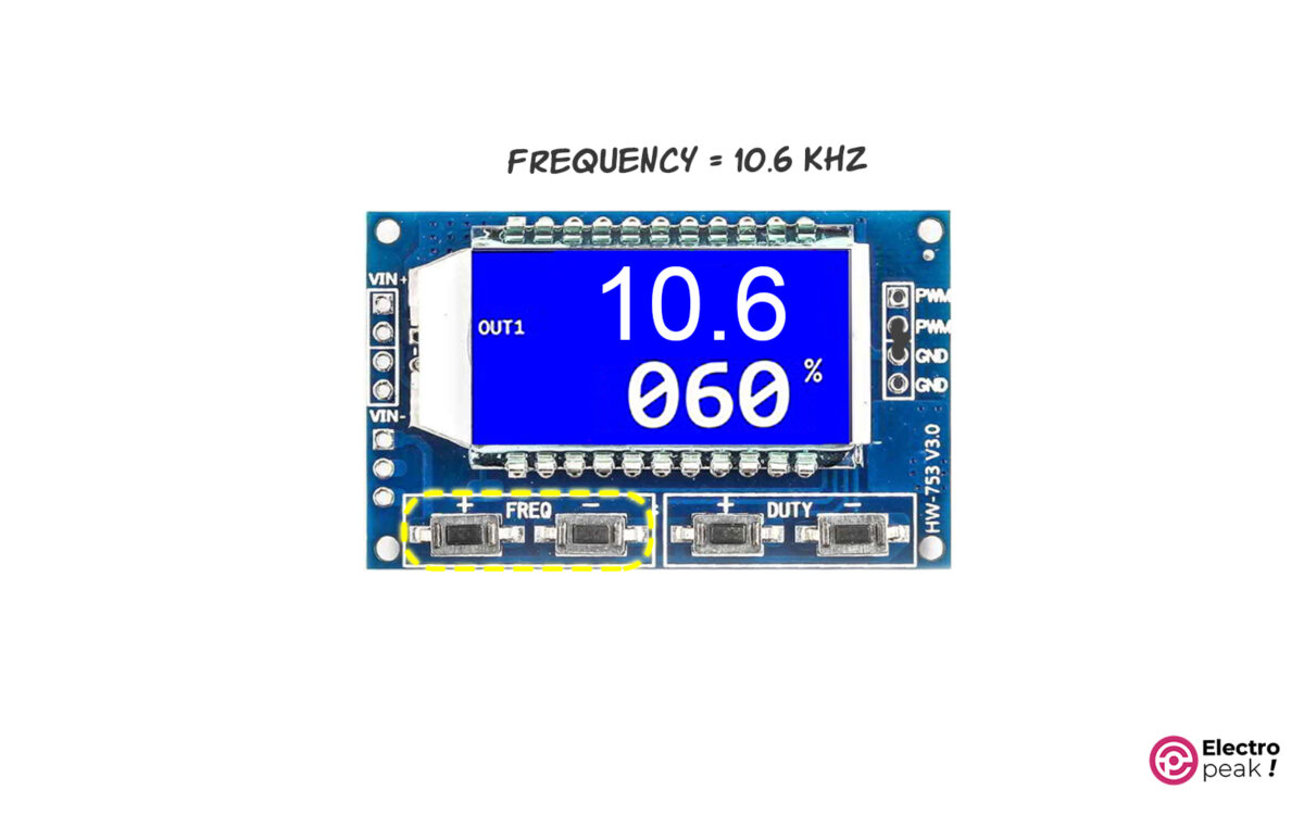
You can see the general screen format in the image above. The first line is the output pulse frequency, and the second line shows the duty cycle percentage of the output pulse signal.
You can observe the module output with an oscilloscope to make sure that you’ve got the desired output frequency and duty cycle.
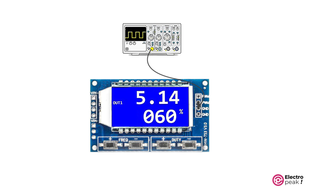
The waveform frequency on the oscilloscope must be equal to the frequency shown on the module screen.
Solution for Output Current Limitation in XY-LPWM Pulse Generator Module
As mentioned, the maximum output current of the XY-LPWM module is 30mA. This current will work perfectly well when using logic circuits because they don’t need a lot of current. But 30mA won’t be nearly enough when running a device such as a DC motor. For such cases, we have to amplify the output current.
One way to increase the output current and power is to use switching circuits. In this method, we use the output signal of the XY-LPWM module as the excitation signal for the switching circuits. Therefore, we can use the switching circuit output to run high-power devices.
There are colorful switching circuits, and most of them are designed based on transistors. Using these circuits, we can run and control an actuator such as a motor (which has a high amount of voltage and current) by a weak excitation signal (which has a low amount of voltage and current). We can get the excitation signal from a microcontroller or any other circuit, such as the XY-LPWM module.
First, let’s briefly explain one type of switching circuit that has a MOSFET transistor.
MOSFET as Switch
The circuit below shows the general form of using a MOSFET in a switching circuit.
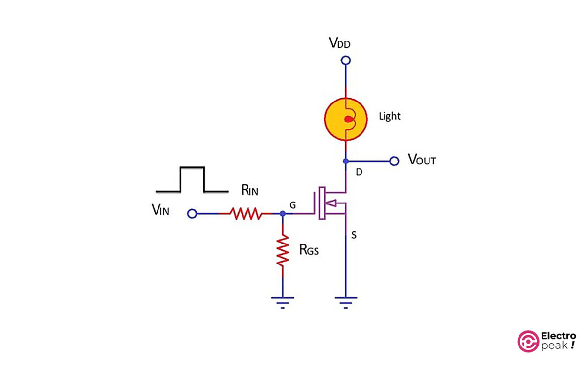
In the above circuit, as the input voltage (VIN) goes up, so does the voltage of the transistor’s gate pin (G). This will activate the transistor, which means, now, there is a connection between the drain pin (D) and the source pin (S), and the current can flow from VDD to GND. As a result, we can turn on a light (or any consumer) in the circuit.
To provide the required excitation signal for the transistor, we should connect the VIN pin to a microcontroller or a circuit. By doing so, the current consumed by the consumer will no longer pass through the VIN pin. In addition, the VDD value, which works as the power supply for the consumer, can be much higher than the excitation voltage. (The voltage and current of “Drain-Source” and “excitation signal” are different in various transistors. So if you need the exact specs of each specific model, you should see their datasheet.)
For example, let’s control a 12V motor with Arduino. Since the voltage of Arduino pins is 5V and their current can be 30mA at most, we can’t connect the Arduino pins, as an output, directly to the motor pin. Solution: The above switching circuit. All you have to do is connect the Arduino’s output pin to VIN, and VDD to the 12V power supply and then replace the light with a motor. In this case, we can activate the power supply circuit of the 12V motor with the Arduino’s 5V signal. Now, we control the speed of a DC motor with a power-switching module.
In this example, we use the HW-517 MOSFET Switching Module as the switching circuit. This module has two AOD4184A Power MOSFETs in parallel, which can provide 15A. In addition, the excitation voltage of the HW-517 module is between 3.3 to 20V, and the output voltage can range from 5 to 36V.
Motor Speed Control by XY-LWPM Pulse Generator Module and MOSFET Switch
Wiring
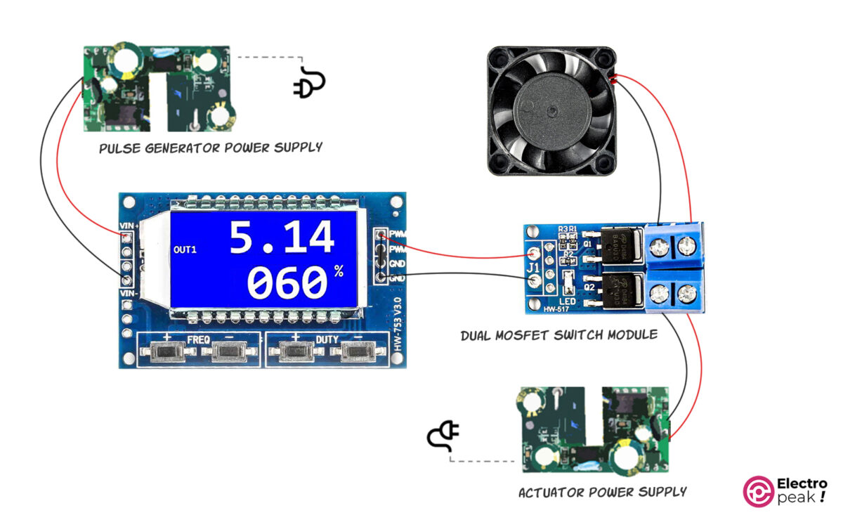
In the above circuit, the output of the XY-LPWM module is given to the switching module as the excitation signal. The MOSFETs are switched on and off with the same frequency and duty cycle as the excitation signal. As a result, the connection between the fan and the power supply on the right side is switched on and off. This way, we can control the average voltage given to the fan by controlling the frequency and duty cycle. In addition, the DC motor speed is proportional to the average voltage.
The power supply on the right side should have a voltage value between 5 to 36 volts; its exact value is determined by the consumer’s operating voltage (here, the fan). Also, we should choose the power supply current according to the actuator current.
If the actuator voltage is between 5 to 20 volts, we can use a typical power supply as long as it can provide the required total current.
We can also use the above circuit to control the color and brightness of RGB LEDs.
XY-LPWM Pulse Generator Module Configuration
Frequency Settings
You can adjust the module frequency from 0 Hz to 150 KHz. To do that, simply press the buttons related to frequency adjustment—the “+” button for increasing the frequency and the “-“ button for decreasing it. Remember that the frequency changes more quickly if you press and hold the buttons.
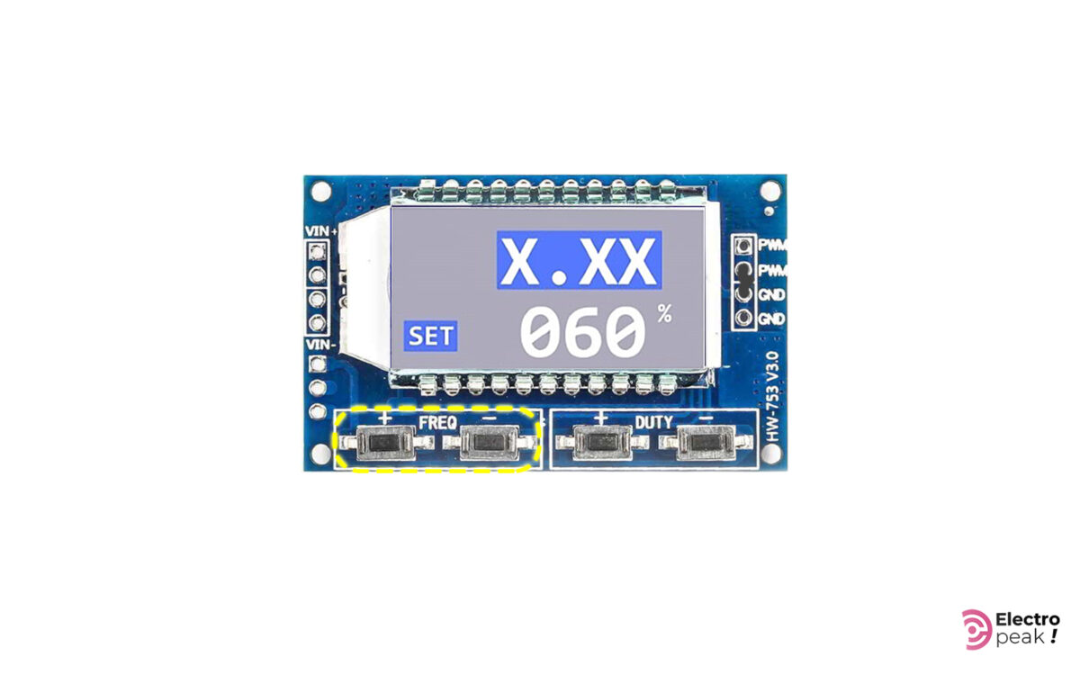
When you are changing the frequency, the word “OUT” disappears, and then the word “SET” appears on the screen. The value related to the frequency also changes on the screen (in the first line).
Here are the formats to display the frequency value:
XXX: In this format, the value is the output frequency represented in Hz. And it ranges from 0 to 999Hz. For example, when you see “300” on the screen, it means 300Hz.

X.XX: The value is represented in “KHz,” and it ranges from 1KHz to 9.99KHz. For example, when you see “1.00” on the screen, it means 1KHz. In addition, whenever you press the related buttons, the frequency changes by 10Hz.

XX.X: The value is represented in tens of KHz, and it ranges from 10.0KHz to 99.9KHz. For example, when you see “10.0” on the screen, it means 10KHz. In addition, whenever you press the related buttons, the frequency changes by 100Hz.
X.X.X: The value is represented in hundreds of KHz, and it ranges from 100KHz to 150KHz. For example, when you see “1.0.0” on the screen, it means 100KHz. In addition, whenever you press the related buttons, the frequency changes by 1KHz.

Duty Cycle Settings
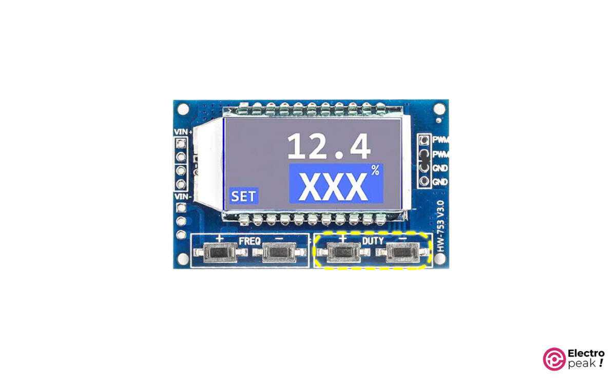
The module’s duty cycle ranges from 0 to 100%. To adjust this parameter, you can press the buttons “+” and “-“ shown in the image above. In addition, the three-digit number on the second line of the screen represents this parameter.
Controlling XY-LPWM Pulse Generator Module with Serial Interface
As mentioned, the module has a serial interface port with a 3.3V logic level. We can adjust the frequency features of the generated wave or restore the adjusted features by some specific commands using the serial port.
If you are using a 5V logic-level microcontroller to communicate with the module, make sure to use a voltage-level converter so as not to damage the pulse generator module.
The serial communication baud rate is 9600.
Frequency Settings
To adjust the frequency, send the data—in a similar format as in the display with an “F” prefix—to the module via the serial interface. Look at the examples below:
• F100: Adjusting the frequency to 100Hz
• F1.00: Adjusting the frequency to 1kHz
• F10.0: Adjusting the frequency to 10kHz
• F1.0.0: Adjusting the frequency to 100kHz
If the module understands the message, it will respond with the word “DOWN”. Otherwise, it will show the word “FAIL.”
Duty Cycle Settings
To adjust the duty cycle, send it to the module with a “D” prefix. Here’s an example:
D050: Adjusting the duty cycle to 50%.
Value Reading
You should send the word “read” to the module to read the module settings.
What’s Next?
With three XY-LPWM modules and three switch modules, as in the second example, build an RGB color controller and adjust the color and brightness of an RGB LED String.
Build a digital-to-analog converter using a pulse generator module and an RC circuit.
Using Arduino, write a code that can both receive the values from the serial port of a computer and then apply it to the module.

Comments (4)
Nicely Explained
you’re welcome
Hi!
Thanks for the description! in the case of XY-LPWM3, what is the appropriate serial command to differentiate each channel??
Hello,
You can download the datasheet from this link, which will provide you with a guide on how to use the Serial interface of this module.