
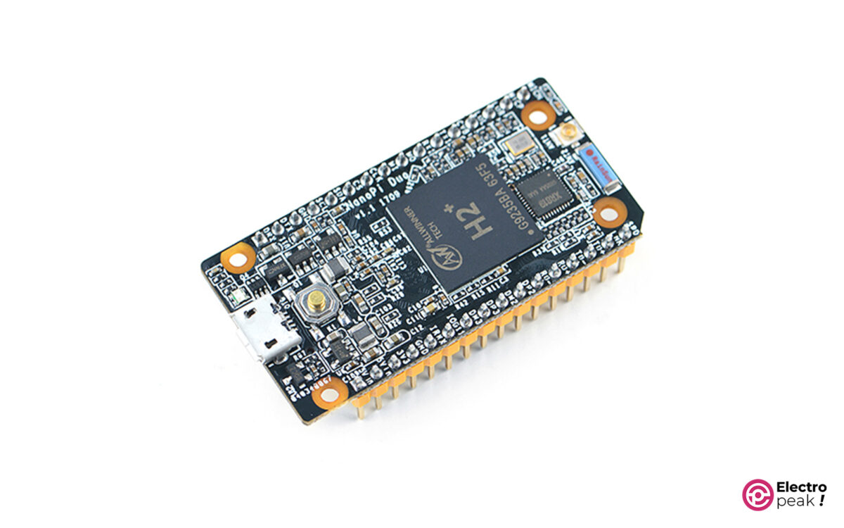
NanoPi Duo Board Features
The NanoPi Duo Board functions like a compact computer, offering a range of features. Its main processor—Allwinner H2+—provides sufficient processing power through its Cortex-A7 quad-core processor. The board also comes with DDR3-type Memory available in two models: 256MB and 512MB.
The NanoPi Duo board includes USB ports that allow you to connect peripherals such as a keyboard, mouse, storage device, or Wi-Fi dongle. In addition, you can connect the internal Ethernet port on the board to access the Internet, transmit data, and communicate over the network at speeds up to 100M. The board also facilitates connections to monitors, TVs with composite video input, microphones, or other audio devices via the CVBS (Composite Video Baseband Signal) and MIC pins.
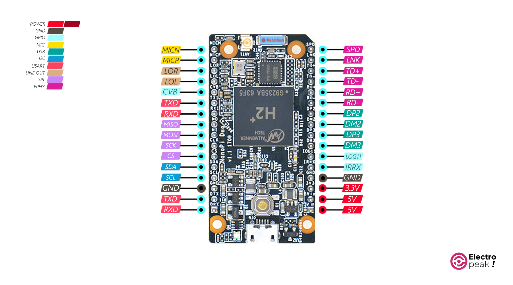
NanoPi Duo Board Pinout
• 5V-3.3V: Output voltage
• GND: Ground
• SCL: Data synchronization for I2C protocol
• SDA: Data information for I2C protocol
• CS: Selecting subset devices for SPI protocol
• SCK: Synchronization for SPI protocol
• MOSI: Data transmission line for SPI protocol
• MISO: Data receiving line for SPI protocol
• TXD: USART data transmitter (connected to the RX pin of the opposing device)
• RXD: USART data receiver (connected to the TX pin of the opposing device)
• CVB: CVBS (Composite Video Baseband Signal) pin used for the output of the composite video signals. Connect this CVBS pin to devices such as TVs or monitors that support composite video input.
• MICP: External microphone connection (positive line or positive signal of the microphone)
• MICN: External microphone connection (negative line or negative signal of the microphone)
• IRRX: Receiving infrared signals (IR)
• LOG11: A GPIO pin as an input and output used for general-purpose applications
• DM-DP: Two data lines used for transmitting and receiving digital signals in USB communication
• RD: Receiving data (Ethernet port)
• TD: Transmitting data (Ethernet port)
• LNK: Displaying the connection status and the Ethernet network communication
• SPD: Displaying the speed of the Ethernet network connection
• LOR: Sound output data for connecting to an external device such as a speaker or amplifier (LOR is the right channel output)
• LOL: Sound output data for connecting to an external device such as a speaker or amplifier (LOL is the left channel output)
You can see the pinout of the NanoPi Duo Board in the image below.
For more information, refer to the datasheet.
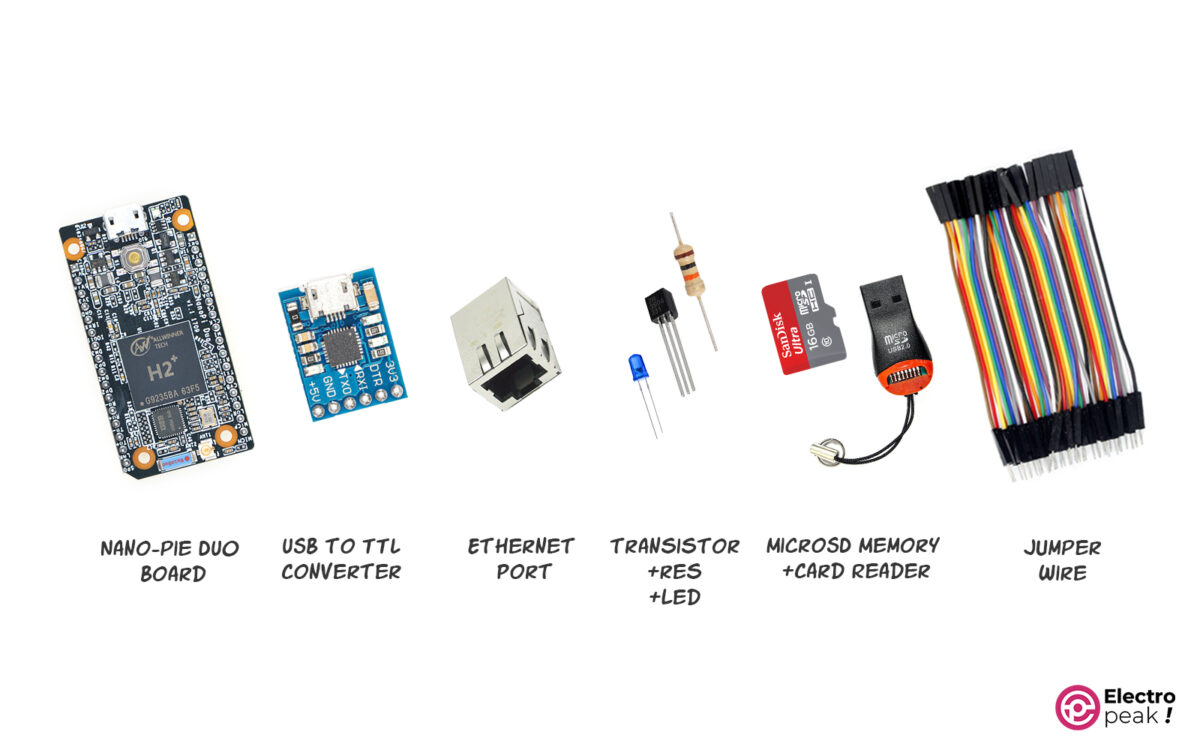
Required Materials
Step 1: Installing FriendlyCore on MicroSD
Connect a compatible MicroSD Memory Card (at least 8GB) to your computer with a card reader.
Here, you can download the Image file of the FriendlyCore operating system for NanoPi Duo.
You can also download and install the Win32DiskImager software from this link.
Using a RAM READER, connect the MicroSD CARD to your computer and then follow the steps below:
1. Run Win32DiskImager on your computer.
2. In Win32DiskImager, click on the folder icon next to “Image File.”
3. Browse to the location where you saved the FriendlyCore OS Image.
4. Select the image file and click “Open.”
5. From the drop-down list in the Device section, select the correct MicroSD Drive.
6. Click the “write” button.
7. Click “Yes” to confirm the following warning message: “All data on the selected drive will be deleted.”
8. Wait for the writing process to complete.
9. When you see the confirmation message, it means that you have successfully installed FriendlyCore OS on your MicroSD Card. You can now use this MicroSD Card to boot your board with FriendlyCore.
10. Insert the MicroSD Card into the NanoPi Duo board.
Step 2: Installing FriendlyCore on NanoPi Duo
Here, you can download and install the appropriate version of Putty Software for your computer.
After that, follow the steps below:
1. Connect the USB-to-Serial Converter to your computer.
2. Connect the converter RX pin to the NanoPi Duo TX pin and vice versa.
3. Connect the GND pin of the USB-to-Serial convertor to the NanoPi Duo GND pin.
4. Run the Putty Software.
5. Open the “Device Manager.”
6. Look for “Ports (COM & LPT)” and open it.
7. Identify the USB-to-Serial port of the converter and note down the port number (e.g., COM1 or COM2). To be sure, you can disconnect and reconnect the converter once.
8. Select “Serial” from the Putty software.
9. Select the COM port related to the USB-to-Serial converter which you noted down.
10. Set the speed to 115200.
11. Click the “Open” button to start the serial connection.
12. Connect the NanoPi Duo to your computer via a USB cable (the board LED should light up).
13. You should now see the FriendlyCore boot process and console output in the Putty terminal window.
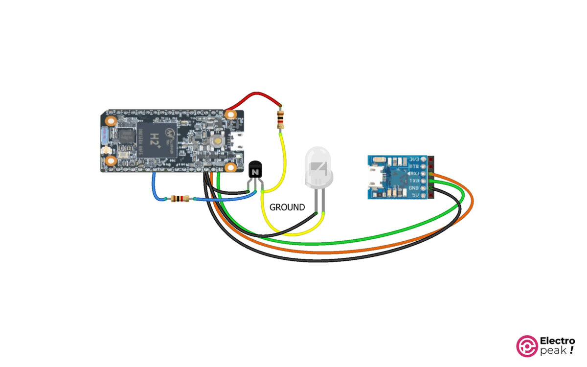
Step 3: Wiring
Connect the wires as shown below.
Note that the LED’s positive pin is connected to the board’s MO pin.
Step 4: Install Libraries on NanoPi Duo
According to the descriptions about the Ethernet Pins, connect an Ethernet port to your NanoPi Duo for a Wi-Fi connection, and then connect it to your modem using a cable. You can run the following command to ensure connectivity.
Ping 1.1.1.1
In the Putty software terminal, run the command below to update Repository.
sudo apt update
Next, install the library using the following command.
sudo apt install wiringpi
Step 5: Upload Code to NanoPi Duo
After installing the library, make a C-type file using the command below.
nano led_blink.c
Now, copy the following code into the file.
/*
Made on May 28, 2023
By Amin Damirchi
Home
*/
#include <wiringPi.h>

#define LED_PIN 7

int main()
{
 wiringPiSetup();
 pinMode(LED_PIN, OUTPUT);

 while (1)
 {
 digitalWrite(LED_PIN, HIGH);
 delay(1000);
 digitalWrite(LED_PIN, LOW);
 delay(1000);
 }
 return 0;
}
Press “Ctrl + X” to save and exit the file. Next, press the “Y” key to save changes, and then press the “Enter” key to confirm the file name.
Compile the file using the following command.
gcc -o led_blink led_blink.c –lwiringPi
Run the compiled code using the command below:
sudo ./led_blink
Now the code turns the LED connected to GPIO 7 on and off with a 1-second delay.
