Contents

Arduino Polygraph Machine (Lie Detector)

Overview

In this project, We’ll try to get some information from human body by using simple sensors and Arduino. You can use these information to create a lie detector machine

What You Will Learn

An Introduction to Polygraph

You may hear about lie detector machines used by FBI or CIA or any another investigation by police. Today we are going to make one of those machines. First of all, let’s figure out one important fact about the polygraph and the lie detector machine. It’s better to say an important fact about lie detection tests. This test cannot tell us the person is lying or telling the truth, by itself. This is very important. But, how do they rely on polygraph test results? The main idea of the lie detection test is changing the reaction of the human body between when a person is telling the truth or answering to a normal and routine question like what’s your name?, And his body reaction when he or she is lying. For example when a criminal is going to have a lie detection test the investigator attach sensors on his finger, head or maybe on his chest. These sensors measure the breathing rate, pulse, blood pressure, perspiration and etc.

Sometimes the machine will also record things like arm, leg, face, and pupil movement. When the test begins the investigator asks some questions like “Is your name, Bob?” or “Do you live in the United States?” When the criminal answers, investigator establish the norm graphs of his reaction. After that, the main questions will be asked. During the test or after that, the investigator checks the result. If he finds a significant change indicates that the criminal is lying. These changes could be faster heart rate, higher blood pressure, increased perspiration, moving and looking around and etc. When an experienced examiner uses a lie detector machine He can detect the lie with high accuracy. If you use the polygraph for the first time it could be a little bit hard for you to recognize the lying.

In this project, We use SHT20 to measure temperature and perspiration, ECG electrodes to measure respiration rate, A pulse sensor to measure heart rate and an Arduino board to get data and analyze them.

Required Materials

Hardware Components

Arduino UNO R3 × 1
Heart Rate Pulse Sensor Module × 1
SHT20 Temperature and Humidity Sensor Module × 1
21cm 40P Male To Female Jumper Wire × 1

Software Apps

Arduino IDE

Circuit

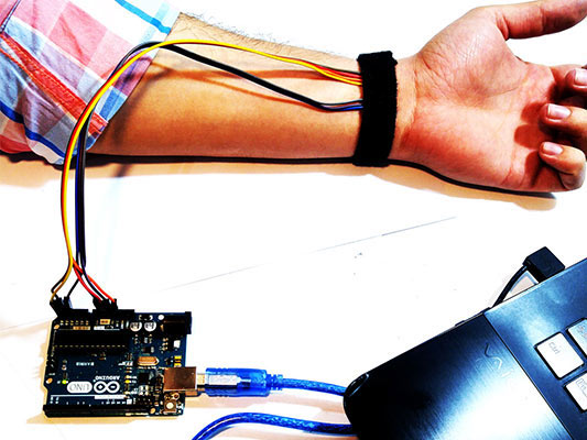
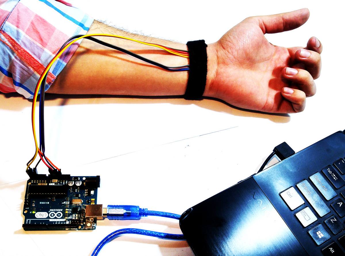
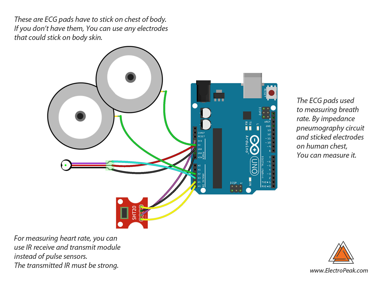
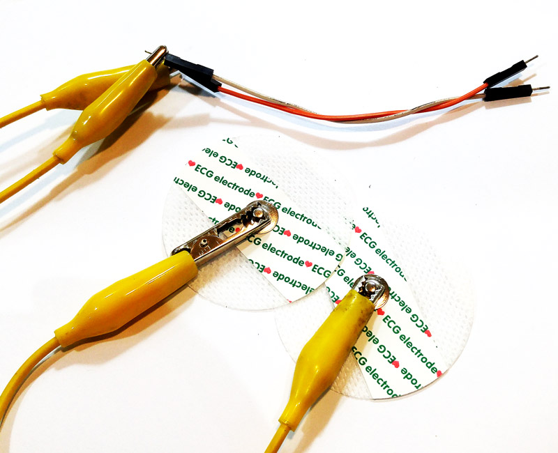
In this circuit, We used ECG pads to have a better connection between the skin of the body and Arduino. You can use alligator clips and jumper wire to make this connection. This circuit can measure the breath rate of the body. But some parts of the circuit is removed from the picture because it depends on the level of parameters resolution and sensitivity in your project. For better understanding, read the impedance pneumography way to measure breath rate and complete your circuit according to your interest.

Code

In this code, We get temperature and perspiration from SHT20 sensor by I2C port, Heart rate from pulse sensor by analog input pin and breath rate from  impedance pneumography circuit by analog input pin.

You must add the library and then upload the code. If it is the first time you run an Arduino board, don’t worry. Just follow these steps:

  1. Go to www.arduino.cc/en/Main/Software and download the software of your OS. Install the IDE software as instructed.
  2. Run the Arduino IDE and clear the text editor and copy the following code in the text editor.
  3. Choose the board in tools and boards, select your Arduino Board.
  4. Connect the Arduino to your PC and set the COM port in tools and port.
  5. Press the Upload (Arrow sign) button.
  6. You are all set!

Necessary Files and Downloads:

#include "Wire.h"
#include "DFRobot_SHT20.h"

DFRobot_SHT20    sht20;

void setup()
{
    Serial.begin(9600);
    sht20.initSHT20();                                  // Init SHT20 Sensor
    delay(100);
    sht20.checkSHT20();                                 // Check SHT20 Sensor
}

void loop()
{
    float humd = sht20.readHumidity();                  // Read Humidity
    float temp = sht20.readTemperature();               // Read Temperature
    Serial.print(temp, 2);
    Serial.print(",");
    Serial.print(analogRead(A3));                 // Read Pulse sensor value
    Serial.print(",");
    Serial.print(humd, 1);
    Serial.print(",");
    Serial.println(analogRead(A2));                 // Read Breath rate  
}

Assembling

All you need to do is just cut the sponge and place the sensors. Then put it on your hand and adjust the stretch rubber and stick it using the hot glue gun.

Now, open up the Tools >> Serial Plotter.

You can see PULSE and BREATH graphs in the plotter of Arduino.

What’s Next?

You can improve this project as you wish. Here are a few suggestions:

  • Use ECG modules and connect them to Arduino
  • Try analyzing data from your body.
  • Make a simple Lie Detector by more sensors and more coding.
Liked What You See?​
Get Updates And Learn From The Best​

Comments (11)

  • NANDU KRISHNAN Reply

    Can we use another temperature and humidity sensors instead of SHT20

    April 5, 2022 at 1:26 pm
    • Mehran Maleki Reply

      Hi,
      Sure, you can use other temperature and humidity sensors. But of course you will need to change the code and circuit according to your new sensor.

      April 7, 2022 at 7:40 am
      • NANDU KRISHNAN Reply

        THANKS FOR THE REPLY!!
        SHT20 IS ALMOST UNAVAILABLE,SO WILL BE USING DHT11 SENSOR.
        CAN YOU SUGGEST THE CHANGES IN ABOVE CODE FOR THE DHT11 SENSOR.
        THANKS IN ADVANCE

        April 7, 2022 at 12:40 pm
        • Mehran Maleki Reply

          You’re welcome!
          DHT11 is a pretty good choice actually. As I said earlier, you just need to make some changes to the code and circuit. Here is a good tutorial on how you can interface DHT11 sensor with Arduino. You can use it to properly modify the code and wiring.
          https://electropeak.com/learn/interfacing-dht11-temperature-humidity-sensor-arduino/

          April 9, 2022 at 6:55 am
          • NANDU KRISHNAN

            Thanks for that!!
            i have setup this project,and included dht11 sensor instead of sht20.The code is fine.
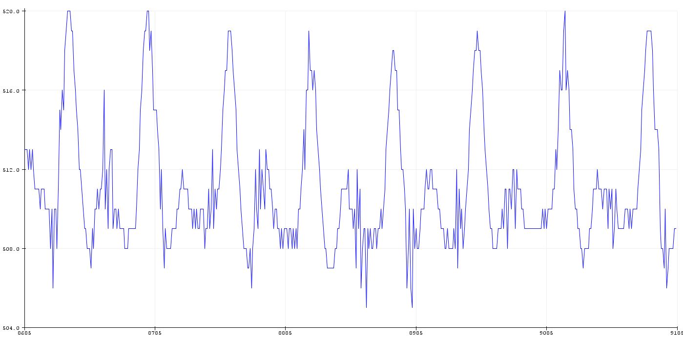
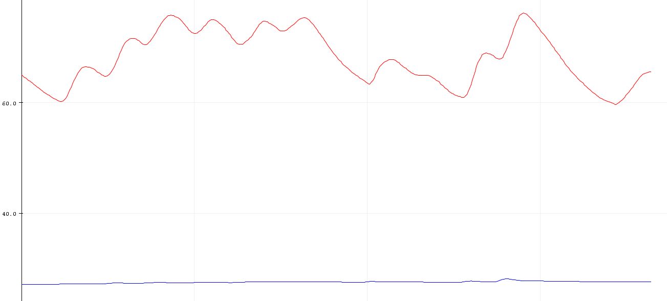
            may i know the expected waveforms,during the experiment,when someone is lying or not.
            How can we differentiate that from the graph.
            Thanks in advance

            April 21, 2022 at 4:23 pm
        • Mehran Maleki Reply

          Hi,
          The expected waveforms are the same as the last images shown in this article. The first waveform plotted in blue and the second one plotted in red are the expected waveforms for when someone is telling a truth or a lie, respectively. -Blue for truth and red for lie –

          April 27, 2022 at 3:11 pm
          • Pavan S

            Can u give full details of code how to compile in Arduino

            June 25, 2022 at 3:58 pm
  • Brian Reply

    Que archivo o código debería modificar para poder utilizar el modelo DHT11?:(

    November 16, 2022 at 10:05 pm
  • Nikola Reply

    Hii, my question is it necessary SHT20 Temperature and Humidity Sensor Module, can lie detector could work without that sensor?

    March 12, 2024 at 12:17 pm
    • Mohammad Damirchi Reply

      Hi Nikola,
      The SHT20 sensor is primarily used to obtain temperature and humidity readings. While it’s possible to exclude this sensor, many lie detectors also incorporate temperature and humidity measurements alongside other data points.

      March 13, 2024 at 6:17 am

Leave a Reply

Your email address will not be published. Required fields are marked *