
Overview
As you might know, the ESP32 board is very popular today because of the amazing capabilities it offers. The fact that you can add features such as Bluetooth and Wi-Fi to projects makes this board a great option for a wide variety of Internet of Things (IoT) projects. But as economists say, “There is no free lunch!” This means that every benefit comes with a cost. These attractive features of ESP32 also come at a cost, which is its high power consumption. The designers of ESP32 have also come up with a solution to this problem: you can put ESP32 into various sleep modes. This tutorial will cover the most comprehensive sleep mode on the ESP32 board, called Deep Sleep mode.
What You Will Learn
- Different power-consuming parts of ESP32 boards
- Different sleep modes in ESP32 boards
- Deep Sleep in ESP32 boards and its various modes
Different Sleep Modes of ESP32
If you plan to use a USB wall adapter or something similar in your project, you will no longer have to worry about power consumption. But if you are planning to use a battery, the power consumption of your project will definitely be very important to you. Due to its Wi-Fi and Bluetooth, the ESP32 can draw up to 260mA, which is why it can drain your battery quickly! As mentioned in the introduction, the designers of ESP32 have considered a solution for this problem: use ESP32 in different sleep modes.
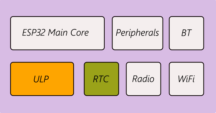
Generally speaking, ESP32 can be divided into seven different parts in terms of energy consumption. These seven parts are as follows:
- WiFi
- Bluetooth
- Radio
- ESP32 core
- Ultra Low Power Coprocessor (ULP Coprocessor)
- Peripherals
- Timer (RTC)
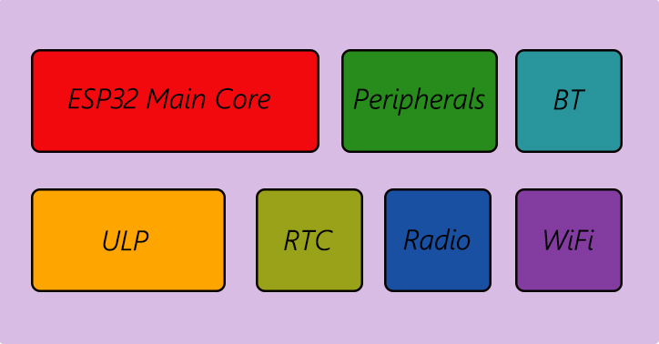
When the ESP32 board is fully active, all parts above are working. But to save energy, you can disable some of these parts by putting the ESP32 board in different sleep modes, which will optimize the power consumption. Below are the different modes into which you can put the ESP32 board.
- Active mode
- Modem sleep mode
- Light sleep mode
- Deep sleep mode
- Hibernation mode
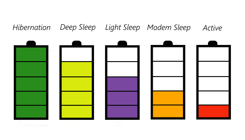
In the active mode, as mentioned, all parts of ESP32 are active, and the power consumption is at its maximum. In Hibernation mode, unlike the active mode, all parts of ESP32 are disabled, and the board returns to normal only if being reset. To save energy, you can use the ESP32 board in different sleep modes, the most optimal of which is Deep Sleep mode, which we will discuss in this tutorial.
ESP32 Deep Sleep Mode Wake-up Sources
As stated earlier, to save energy, we can put the ESP32 board into different sleep modes to turn off some parts of it. The most ideal sleep mode in ESP32 is its Deep Sleep mode. In this mode, only two of the seven main ESP32 parts remain active and the rest are deactivated. These two parts are:
- Ultra Low Power Coprocessor (ULP Coprocessor)
- timer (RTC).
You may have been wondering what happens after ESP32 is put into Deep Sleep mode. How to wake it up if needed? Well, the designers have offered various methods in order to wake ESP32 from Deep Sleep mode. These methods are as follows:
- Use the timer to wake the ESP32 from sleep at specific intervals (e.g. every 2 hours, every day, …)
- Touch pins
- External Wake-up
- ULP Coprocessor
The last method is not discussed in this tutorial. In the following, the first three methods are fully examined.
Required Material
Hardware Components
Software Apps
**The board we have used here is the NodeMCU – ESP32S Edition board. But if you have another ESP32-based board, you can still follow the same tutorial and code.
ESP32 Deep Sleep Wake-up Source: Timer
The easiest way to wake ESP32 from deep sleep is to use the Timer. In this method, we first set how long we want the ESP32 to stay asleep. And then, we put it into deep sleep mode. Then, the CPU and timer components that are still active will wake the ESP32 on time.
Code
To put ESP32 into Deep Sleep and wake it up with Timer, upload the following code on your ESP32.
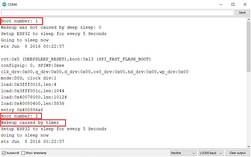
By programming your ESP32 board with the code above, the board goes into Deep Sleep mode and wakes up every 5 seconds by the Timer. Then, it goes back to sleep. The output of this code in Serial Monitor is as follows:
/*
Modified on Jul 12, 2021
Modified by MehranMaleki from Arduino Examples
Home
*/


#define uS_TO_S_FACTOR 1000000 /* Conversion factor for micro seconds to seconds */
#define TIME_TO_SLEEP 5 /* Time ESP32 will go to sleep (in seconds) */


RTC_DATA_ATTR int bootCount = 0;


//Function for printing the reason by which ESP32 has been awakened from sleep
void print_wakeup_reason(){
 esp_sleep_wakeup_cause_t wakeup_reason;

 wakeup_reason = esp_sleep_get_wakeup_cause();
 switch(wakeup_reason)
 {
 case ESP_SLEEP_WAKEUP_EXT0 : Serial.println("Wakeup caused by external signal using RTC_IO"); break;
 case ESP_SLEEP_WAKEUP_EXT1 : Serial.println("Wakeup caused by external signal using RTC_CNTL"); break;
 case ESP_SLEEP_WAKEUP_TIMER : Serial.println("Wakeup caused by timer"); break;
 case ESP_SLEEP_WAKEUP_TOUCHPAD : Serial.println("Wakeup caused by touchpad"); break;
 case ESP_SLEEP_WAKEUP_ULP : Serial.println("Wakeup caused by ULP program"); break;
 default : Serial.printf("Wakeup was not caused by deep sleep: %d\n",wakeup_reason); break;
 }
}

void setup(){
 Serial.begin(115200);
 delay(500);

 //Increment boot number and print it every reboot
 bootCount++;
 Serial.println("Boot number: " + String(bootCount));

 //Print the wakeup reason for ESP32
 print_wakeup_reason();

 /*
 1st Step: we should configure the wake up source:
 We set our ESP32 to use "Timer" to wake up every 5 seconds
 */
 esp_sleep_enable_timer_wakeup(TIME_TO_SLEEP * uS_TO_S_FACTOR);
 Serial.println("Setup ESP32 to sleep for every " + String(TIME_TO_SLEEP) + " Seconds");


 /*
 2nd Step: we can decide what peripherals to shut down or keep on.
 By default, ESP32 will automatically power down all peripherals
 not needed by the wakeup source. But if you want to configure peripherals on your own, read the details in the API docs:
 http://esp-idf.readthedocs.io/en/latest/api-reference/system/deep_sleep.html
 The comment line below is an example of how to configure peripherals. It turns off all RTC peripherals in deep sleep mode. You can leave that comment.
 */
 //esp_deep_sleep_pd_config(ESP_PD_DOMAIN_RTC_PERIPH, ESP_PD_OPTION_OFF);


 /*
 3rd Step: Now that we have setup a wake cause, and if needed, setup the peripherals state in deep sleep mode, we can now start going to deep sleep.
 If you have provided no wake up sources but the deep
 sleep has been started, it will sleep forever unless hardware
 reset occurs.
 */
 Serial.println("Going to sleep now");
 delay(500);
 esp_deep_sleep_start();
 Serial.println("This will never be printed");
}

void loop(){
 //This will not be used in Deep Sleep mode.
}
In the following, we are going to explain the different parts of the code.
#define uS_TO_S_FACTOR 1000000  /* Conversion factor for micro seconds to seconds */
#define TIME_TO_SLEEP  5        /* Time ESP32 will go to sleep (in seconds) */
At the beginning of the code, two integers are defined. In fact, ESP32 sleep duration should be set in microseconds. Since, in this tutorial, we want to work in seconds, we have defined these two numbers to make it easier to program. To change the sleep duration of ESP32, just apply the desired change in this section.
RTC_DATA_ATTR int bootCount = 0;
RTC_DATA_ATTR as shown above. //Function for printing the reason by which ESP32 has been awakened from sleep
void print_wakeup_reason(){
esp_sleep_wakeup_cause_t wakeup_reason;
wakeup_reason = esp_sleep_get_wakeup_cause();
switch(wakeup_reason)
{
case ESP_SLEEP_WAKEUP_EXT0 : Serial.println("Wakeup caused by external signal using RTC_IO"); break;
case ESP_SLEEP_WAKEUP_EXT1 : Serial.println("Wakeup caused by external signal using RTC_CNTL"); break;
case ESP_SLEEP_WAKEUP_TIMER : Serial.println("Wakeup caused by timer"); break;
case ESP_SLEEP_WAKEUP_TOUCHPAD : Serial.println("Wakeup caused by touchpad"); break;
case ESP_SLEEP_WAKEUP_ULP : Serial.println("Wakeup caused by ULP program"); break;
default : Serial.printf("Wakeup was not caused by deep sleep: %d\n",wakeup_reason); break;
}
}
Here, we have defined a function that can be used to display the cause of the ESP32 wake-up in the Serial Monitor after each wake-up. As you can see in the code, these reasons can be either EXT0, EXT1, TIMER, TOUCHPAD, or ULP. We will use this function in later steps, too.
void setup(){
Serial.begin(115200);
delay(500);
//Increment boot number and print it every reboot
bootCount++;
Serial.println("Boot number: " + String(bootCount));
//Print the wakeup reason for ESP32
print_wakeup_reason();
After defining the function in the previous step, we go into the program setup. In Deep Sleep mode, we only have the setup part, and all of our code will be in this part. In fact, at the end of the setup, the ESP32 goes into Deep Sleep mode, and as a result, we will never enter the loop part. In the setup, we first make the necessary settings to display the results in Serial Monitor. Each time the program reaches the beginning of the setup, it means that ESP32 has woken up from Deep Sleep mode, so we increase the variable stored in the RTC memory by one and display it on the Serial Monitor. Then, the cause of ESP32 waking up is displayed.
/*
1st Step: we should configure the wake up source:
We set our ESP32 to use "Timer" to wake up every 5 seconds
*/
esp_sleep_enable_timer_wakeup(TIME_TO_SLEEP * uS_TO_S_FACTOR);
Serial.println("Setup ESP32 to sleep for every " + String(TIME_TO_SLEEP) + " Seconds");
To put ESP32 into Deep Sleep mode, we first need to adjust the ESP32 wake-up source. In this part of the tutorial, we are going to do this with the Timer method. To set the Timer as the ESP32 wake-up cause, we can use the “esp_sleep_enable_timer_wakeup (time in us)” function. This function takes time in microseconds and uses the Timer method as the source for waking ESP32 from Deep Sleep mode.
/*
2nd Step: we can decide what peripherals to shut down or keep on.
By default, ESP32 will automatically power down all peripherals
not needed by the wakeup source. But if you want to configure peripherals on your own, read the details in the API docs:
http://esp-idf.readthedocs.io/en/latest/api-reference/system/deep_sleep.html
The comment line below is an example of how to configure peripherals. It
turns off all RTC peripherals in deep sleep mode. You can leave that comment.
*/
//esp_deep_sleep_pd_config(ESP_PD_DOMAIN_RTC_PERIPH, ESP_PD_OPTION_OFF);
At this point, we can configure parts of ESP32 that are disabled in Deep Sleep mode. By default, ESP32 disables all the parts that are non needed to wake up the ESP32. So, you can skip this step.
/*
3rd Step: Now that we have set up a wake cause, and if needed, setup the
peripherals state in deep sleep mode, we can now start going to
deep sleep.
If you have provided no wake up sources but the deep
sleep has been started, it will sleep forever unless hardware
reset occurs.
*/
Serial.println("Going to sleep now");
delay(500);
esp_deep_sleep_start();
Serial.println("This will never be printed");
}
At this stage, which is the final one, after the settings made in the previous steps, we can now put the ESP32 board into Deep Sleep mode. To do this, we can use the “esp_deep_sleep_start()” command. With this command line, the ESP32 board goes into Deep Sleep and stays asleep for the set time. After ESP32 wakes up, the setup will be run from the beginning. As a result, as mentioned earlier, the code never reaches the part after the command line of “esp_deep_sleep_start().”
In this section, we fully discussed how to put ESP32 into Deep Sleep mode and wake it up with the help of a Timer. Next, we will discuss other methods.
ESP32 Deep Sleep Wake-up Source: Touch Pins
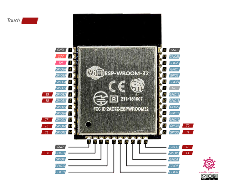
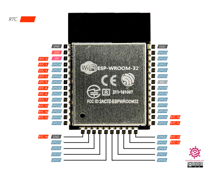
As you probably know, the ESP32 board has pins that can act as a touch sensor. These pins in the ESP-WROOM-32 microcontroller, which is the main microcontroller in most ESP32 boards, are as follows:
- T0 (GPIO 4)
- T1 (GPIO 0)
- T2 (GPIO 2)
- T3 (GPIO 15)
- T4 (GPIO 13)
- T5 (GPIO 12)
- T6 (GPIO 14)
- T7 (GPIO 27)
- T8 (GPIO 33)
- T9 (GPIO 32)
For complete information on the different types of pins available in ESP32, you can refer to the following tutorial.
ESP32 Microcontroller Pinout Reference
In addition to being used as touch sensors, they can also be used to wake the ESP32 board from Deep Sleep mode. In this mode, we determine which touchpad wakes the ESP32 microcontroller from Deep Sleep mode. In this method, the board goes into Deep Sleep, and the ULP Coprocessor and the RTC parts that are still active constantly check the touch pins, and once the desired pin is touched, the ESP32 board wakes up from Deep Sleep mode.
Code
To put ESP32 into Deep Sleep mode and wake it up with touchpads, upload the following code to your ESP32 board.
/*
Modified on Jul 12, 2021
Modified by MehranMaleki from Arduino Examples
Home
*/
#define Threshold 40 /* Greater the value, more the sensitivity */
RTC_DATA_ATTR int bootCount = 0;
//Function for printing the reason by which ESP32 has been awakened from sleep
void print_wakeup_reason(){
  esp_sleep_wakeup_cause_t wakeup_reason;

  wakeup_reason = esp_sleep_get_wakeup_cause();
  switch(wakeup_reason)
  {
    case ESP_SLEEP_WAKEUP_EXT0 : Serial.println("Wakeup caused by external signal using RTC_IO"); break;
    case ESP_SLEEP_WAKEUP_EXT1 : Serial.println("Wakeup caused by external signal using RTC_CNTL"); break;
    case ESP_SLEEP_WAKEUP_TIMER : Serial.println("Wakeup caused by timer"); break;
    case ESP_SLEEP_WAKEUP_TOUCHPAD : Serial.println("Wakeup caused by touchpad"); break;
    case ESP_SLEEP_WAKEUP_ULP : Serial.println("Wakeup caused by ULP program"); break;
    default : Serial.printf("Wakeup was not caused by deep sleep: %d\n",wakeup_reason); break;
  }
}
//Function for printing the touchpad by which ESP32 has been awakened from sleep
void print_wakeup_touchpad(){
touch_pad_t touchPin;
touchPin = esp_sleep_get_touchpad_wakeup_status();
switch(touchPin)
{
case 0 : Serial.println("Touch detected on GPIO 4"); break;
case 1 : Serial.println("Touch detected on GPIO 0"); break;
case 2 : Serial.println("Touch detected on GPIO 2"); break;
case 3 : Serial.println("Touch detected on GPIO 15"); break;
case 4 : Serial.println("Touch detected on GPIO 13"); break;
case 5 : Serial.println("Touch detected on GPIO 12"); break;
case 6 : Serial.println("Touch detected on GPIO 14"); break;
case 7 : Serial.println("Touch detected on GPIO 27"); break;
case 8 : Serial.println("Touch detected on GPIO 33"); break;
case 9 : Serial.println("Touch detected on GPIO 32"); break;
default : Serial.println("Wakeup not by touchpad"); break;
}
}
void callback(){
//write instructions you want to be performed when the ESP32 wakes up
}
void setup(){
Serial.begin(115200);
delay(500);
//Increment boot number and print it every reboot
bootCount++;
Serial.println("Boot number: " + String(bootCount));
//Print the wakeup reason for ESP32 and aslo the touchpad
print_wakeup_reason();
print_wakeup_touchpad();
/*
1st Step: we should configure the wake up source:
We set our ESP32 to use "TouchPad 3 (GPIO15)" to wake up
To do that, we first need to setup interrupt on one of
the touch pins -in our case "Touch Pad 3"- and then,
configure "Touchpad" as the wakeup source.
*/
//Setup interrupt on Touch Pad 3 (GPIO15)
touchAttachInterrupt(T3, callback, Threshold);
//Configure Touchpad as wakeup source
esp_sleep_enable_touchpad_wakeup();
/*
2nd Step: we can decide what peripherals to shut down or keep on.
By default, ESP32 will automatically power down all peripherals
not needed by the wakeup source. But if you want to configure peripherals
on your own, read the details in the API docs:
http://esp-idf.readthedocs.io/en/latest/api-reference/system/deep_sleep.html
The comment line below is an example of how to configure peripherals. It
turns off all RTC peripherals in deep sleep mode. You can leave that comment.
*/
//esp_deep_sleep_pd_config(ESP_PD_DOMAIN_RTC_PERIPH, ESP_PD_OPTION_OFF);
/*
3rd Step: Now that we have set up a wake cause, and if needed, setup the
peripherals state in deep sleep mode, we can now start going to
deep sleep.
If you have provided no wake up sources but the deep
sleep has been started, it will sleep forever unless hardware
reset occurs.
*/
Serial.println("Going to sleep now");
delay(500);
esp_deep_sleep_start();
Serial.println("This will never be printed");
}
void loop(){
//This will not be used in Deep Sleep mode.
}
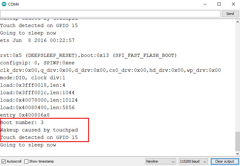
By programming your ESP32 board with the code above, the board goes into Deep Sleep mode and wakes up from Deep Sleep by touching the T3 pin, which is equivalent to GPIO15, and goes back to sleep after performing the desired tasks. The output of this code in the Serial Monitor is as follows:
In the following, we will explain the different parts of the code.
#define Threshold 40 /* Greater the value, more the sensitivity */
At the beginning of the code, a number is defined as Threshold. In fact, each of the ESP32 touch pins is an analog pin that returns a number between 0 and 4095 to the main processor. The way these touchpads work is that they will return a smaller number if touched. Usually, in the case of touch, the number that is returned by the touch pin is around 80. In this part of the code, we define the value which is used to indicate that the touchpad is touched. It is obvious that the higher the value of the defined number, the higher the sensitivity.
Next, as before, we define an integer variable in the RTC memory that stores the number of ESP32 boot times.
Then, similar to the previous method, we define a function to display the cause of the wake-up in the Serial Monitor after each ESP32 wake-up.
//Function for printing the touchpad by which ESP32 has been awakened from sleep
void print_wakeup_touchpad(){
touch_pad_t touchPin;
touchPin = esp_sleep_get_touchpad_wakeup_status();
switch(touchPin)
{
case 0 : Serial.println("Touch detected on GPIO 4"); break;
case 1 : Serial.println("Touch detected on GPIO 0"); break;
case 2 : Serial.println("Touch detected on GPIO 2"); break;
case 3 : Serial.println("Touch detected on GPIO 15"); break;
case 4 : Serial.println("Touch detected on GPIO 13"); break;
case 5 : Serial.println("Touch detected on GPIO 12"); break;
case 6 : Serial.println("Touch detected on GPIO 14"); break;
case 7 : Serial.println("Touch detected on GPIO 27"); break;
case 8 : Serial.println("Touch detected on GPIO 33"); break;
case 9 : Serial.println("Touch detected on GPIO 32"); break;
default : Serial.println("Wakeup not by touchpad"); break;
}
}
Here, we have defined a function that displays the touch pin has been touched on the Serial Monitor.
void callback(){
//write instructions you want to be performed when the ESP32 wakes up
}
callback(). This function, as described in the comment in the code, is related to the tasks that we want ESP32 to perform after each wake-up by touching the touchpad. This function is empty in our code, and you can put the tasks as you wish. (For example, a simple task such as turning on an LED, reading a sensor, etc.)
Next, we enter the setup part of the code. We make the initial settings for the Serial similar to the previous method, and then, update the variable defined in the RTC memory.
After following the steps above, we will see the main parts of the code that are used to put the ESP32 into Deep Sleep mode. To fully explain each of these sections, a comment is written before each step that fully explains it. /*
1st Step: we should configure the wake up source:
We set our ESP32 to use "TouchPad 3 (GPIO15)" to wake up
To do that, we first need to set up interrupt on one of
the touch pins -in our case "Touch Pad 3"- and then,
configure "Touchpad" as the wakeup source.
*/
//Setup interrupt on Touch Pad 3 (GPIO15)
touchAttachInterrupt(T3, callback, Threshold);
//Configure Touchpad as wakeup source
esp_sleep_enable_touchpad_wakeup();
touchAttachInterrupt(Pin, Function, Threshold) function to do that. This function has three inputs:
- Pin: The touch pin on which we want to set the interrupt. (In our case, T3)
- Function: The function we want to be performed if an interrupt occurs. (In our code, the “callback” function)
- Threshold: The value that indicates the sensitivity of the touch pin. (In our code, we have defined it as “Threshold” at the beginning.)
esp_deep_sleep_start() command. After executing this command, ESP32 goes into Deep Sleep and only wakes up by touching the desired pin (or pins) and returns to Deep Sleep mode after performing the relevant tasks.
In this section, we looked at how to put ESP32 into Deep Sleep mode and wake it up with the help of ESP32 touchpads. Next, we will look at the last method to wake ESP32 from Deep Sleep. ESP32 Deep Sleep Wake-up Source: External Wake-up
If you have read the ESP32 Microcontroller Pinout Reference tutorial, you must have noticed that one of the functions of the RTC pins is to wake ESP32 from Deep Sleep mode.
In fact, this method of waking up the ESP32 board from Deep Sleep mode is with the help of RTC pins. The following are the RTC pins of the ESP-WROOM-32 microcontroller, which is the main microcontroller on most ESP32 boards.
- RTC_GPIO0 (GPIO 36)
- RTC_GPIO3 (GPIO 39)
- RTC_GPIO4 (GPIO 34)
- RTC_GPIO5 (GPIO 35)
- RTC_GPIO6 (GPIO 25)
- RTC_GPIO7 (GPIO 26)
- RTC_GPIO8 (GPIO 33)
- RTC_GPIO9 (GPIO 32)
- RTC_GPIO10 (GPIO 4)
- RTC_GPIO11 (GPIO 0)
- RTC_GPIO12 (GPIO 2)
- RTC_GPIO13 (GPIO 15)
- RTC_GPIO14 (GPIO 13)
- RTC_GPIO15 (GPIO 12)
- RTC_GPIO16 (GPIO 14)
- RTC_GPIO17 (GPIO 27)
There are two ways to put ESP32 into Deep Seep and wake it up by External Wake-up.
- Ext0: we wake the ESP32 from Deep Sleep mode using a special pin.
- Ext1: we wake the ESP32 from Deep Sleep mode using multiple pins.
These two ways are very similar, but we will examine each separately to better understand them.
Ext0 method:
In this method, as mentioned, we wake ESP32 from Deep Sleep using a special pin. In this case, we select one of the RTC pins and set it to wake the ESP32 up from Deep Sleep mode when that pin becomes LOW or HIGH.
Ext1 method:
In this method, we select a number of RTC pins and determine when we want the ESP32 to wake up from Deep Sleep mode. There are two ways possible to do this.
- All pins become LOW. (ESP_EXT1_WAKEUP_ALL_LOW)
- At least one of the selected pins becomes HIGH. (ESP_EXT1_WAKEUP_ANY_HIGH)
If we want to detect a pin being LOW, we PULL UP that pin.
If we want to detect a pin being HIGH, we PULL DOWN that pin.
The resistor used for pulling up/down can be between 1KΩ to 100KΩ.
Code
Due to the similarity of the ext0 and ext1 methods, their corresponding code is provided in the same code. The only difference between the code for ext0 and ext1 is two lines, which we will explain later.
To put ESP32 to Deep Sleep and wake it up with External Wake-up using RTC pins, upload the following code to your ESP32.
/*
Modified on Jul 12, 2021
Modified by MehranMaleki from Arduino Examples
Home
*/
#include "driver/rtc_io.h"
RTC_DATA_ATTR int bootCount = 0;
//Function for printing the reason by which ESP32 has been awakened from sleep
void print_wakeup_reason(){
esp_sleep_wakeup_cause_t wakeup_reason;
wakeup_reason = esp_sleep_get_wakeup_cause();
switch(wakeup_reason)
{
case ESP_SLEEP_WAKEUP_EXT0 : Serial.println("Wakeup caused by external signal using RTC_IO"); break;
case ESP_SLEEP_WAKEUP_EXT1 : Serial.println("Wakeup caused by external signal using RTC_CNTL"); break;
case ESP_SLEEP_WAKEUP_TIMER : Serial.println("Wakeup caused by timer"); break;
case ESP_SLEEP_WAKEUP_TOUCHPAD : Serial.println("Wakeup caused by touchpad"); break;
case ESP_SLEEP_WAKEUP_ULP : Serial.println("Wakeup caused by ULP program"); break;
default : Serial.printf("Wakeup was not caused by deep sleep: %d\n",wakeup_reason); break;
}
}
void setup(){
  Serial.begin(115200);
  delay(500);

  //Increment boot number and print it every reboot
  bootCount++;
  Serial.println("Boot number: " + String(bootCount));

  //Print the wakeup reason for ESP32
  print_wakeup_reason();
/*
1st Step: we should configure the wake up source:
We set our ESP32 to use "ext0 OR ext1" to wake up
*/
//lines of code used for ext0
//rtc_gpio_pulldown_en(GPIO_NUM_33);
//esp_sleep_enable_ext0_wakeup(GPIO_NUM_33,1); //1 = High, 0 = Low
//lines of code used for ext1
#define BUTTON_PIN_BITMASK 0x300000000
esp_sleep_enable_ext1_wakeup(BUTTON_PIN_BITMASK,ESP_EXT1_WAKEUP_ANY_HIGH);
/*
2nd step: After setting up a wake cause,
we can now start going to deep sleep.
*/
Serial.println("Going to sleep now");
delay(500);
esp_deep_sleep_start();
Serial.println("This will never be printed");
}
void loop(){
//This will not be used in Deep Sleep mode.
}
By programming your ESP32 board with the code above, the board will go into the Deep Sleep mode and wakes up from it either
- With the RTC_GPIO8 pin—equivalent to GPIO33—becoming HIGH (the ext0 method),
- Or with each of the RTC_GPIO8 and RTC_GPIO9 pins—equivalent to GPIO33 and GPIO32—becoming HIGH (the ext1 method).
In the following, we will fully explain the code. (In this code, for more simplicity, we have removed step 2, which was about selecting the parts that are disabled during Deep Sleep.)
#include "driver/rtc_io.h"
At the beginning of the code, we have added “driver / rtc_io.h” to the program. As mentioned earlier, in the External Wake-up method, the pins used must be pulled up/down. In ESP32, there are internal resistors for this purpose. That is, by some settings in the code, the pins can easily be pulled up/down. To use this feature, you need to add the line “include “driver / rtc_io.h” to the code. How to pull up/down a pin will be described later.
In the following, as in the previous methods, we define an integer variable in the RTC memory. Then, we define a function that can be used to display the cause of ESP32 wake-up in the Serial Monitor after each wake-up. Next, in the setup, we first make the necessary settings for displaying data in the Serial Monitor.
Once the steps above are done, we are ready to write the code related to putting the ESP32 board into Deep Sleep mode and waking it up by the External Wake-up method.
The first step is to set up the cause to wake the ESP32 up from Deep Sleep. We do this for the ext0 and ext1 modes, respectively.
/*
  1st Step: we should configure the wake up source:
  We set our ESP32 to use "ext0 OR ext1" to wake up
  */
  lines of code used for ext0
  rtc_gpio_pulldown_en(GPIO_NUM_33);
  esp_sleep_enable_ext0_wakeup(GPIO_NUM_33,1); //1 = High, 0 = Low
For the ext0 method, we should use the command line esp_sleep_enable_ext0_wakeup(GPIO_NUM_X, mode). This command takes the pin number as the first input and the state—HIGH or LOW—that wakes the ESP32 from Deep Sleep as the second input. For the first input, replace the pin number you want with X. The mode input can also be HIGH or LOW.
For PULLUP or PULLDOWN using the internal resistors, we can use the command lines rtc_gpio_pullup_en(GPIO_NUM_X) or rtc_gpio_pulldown_en(GPIO_NUM_X).
 //lines of code used for ext1
  #define BUTTON_PIN_BITMASK 0x300000000
  esp_sleep_enable_ext1_wakeup(BUTTON_PIN_BITMASK,ESP_EXT1_WAKEUP_ANY_HIGH);
esp_sleep_enable_ext1_wakeup(BUTTON_PIN_BITMASK, mode) to set the wake-up cause of our ESP32 board. This command gets a hex number as the first input, which indicates the desired pins. The easiest way to understand how to make this number is to write it in binary. As follows:
0000 0011 0000 0000 0000 0000 0000 0000 0000 0000 0000
Each digit of this 40-digit binary number represents the pins from GIPO0 to GPIO39. Each of the digits being 1 means that the corresponding pin is used for the ext1 method. Then, we convert the resulting binary number to hex and use it in the code. In our example, this number is 0x30000000. (GPIO32 and GPIO33) The second input of the command is the mode, which can be either “ESP_EXT1_WAKEUP_ALL_LOW” or “ESP_EXT1_WAKEUP_ANY_HIGH.”
/*
  2nd step: After setting up a wake cause,
  we can now start going to deep sleep.
  */
  Serial.println("Going to sleep now");
  delay(500);
  esp_deep_sleep_start();
  Serial.println("This will never be printed");
  }
After completing the settings for the ESP32 wake-up method, we can put it into Deep Sleep mode. To do this, we do exactly the same as the previous methods.
In this tutorial, we have thoroughly reviewed the various Deep Sleep modes in the ESP32 microcontroller, and from now on we can use this mode to control the power consumption of this microcontroller in an optimal way.
What’s Next?
By connecting a temperature sensor and SD card module to an ESP32 board, write a program that wakes the ESP32 from the Deep Sleep mode every 6 hours, reads the temperature, saves it to the SD card, and then goes back to deep sleep.

Comment (1)
[…] The “ESP32 Deep Sleep” tutorial […]