
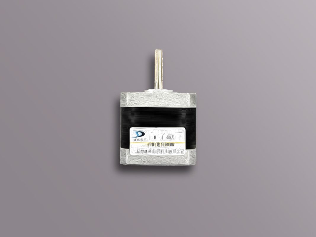
BYGH403 1.65A Stepper Motor Features
Stepper motors are one of the most widely used motors in robotics and electronics. These motors are actually the same as DC motors that move in discrete steps. They have multiple coils called “phases”. By supplying each phase in sequence, the motor will rotate one step (the angle of each step for each motor is specified in its datasheet). with controlling these pulses precisely, you can achieve very precise speed control.
Applications:
- CNC
- 3D printers
- Inkjet printers
- Scanners
- Plotters
- DVD Driver
- and any other item that requires angle control and precise control.
Features:
- Rotation angle: 1.8 degrees
- allowable current: 1.65A
- Phase resistance: 1.5 ohms
- Phase inductance: 2.7mAh
- Maximum allowable voltage: 30V
- Torque index: 3.5Kg/cm
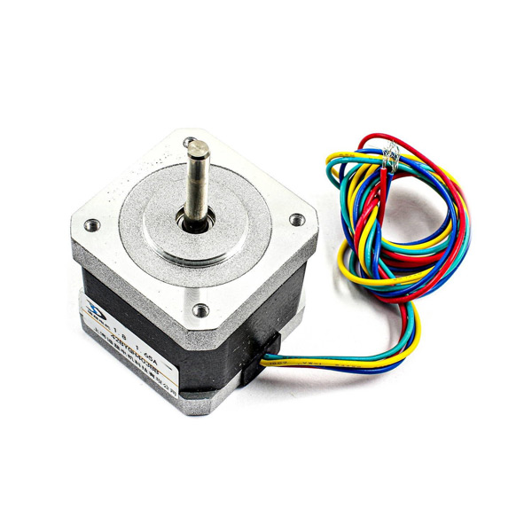
BYGH403 Stepper Motor Pinout
This driver has 4 wires: Green, Red, Yellow and Blue. The red and green wires are for one phase and the yellow and blue wires are for the other phase.
Note
If you want to detect the phases, you can use a multimeter. First put the multimeter in beep mode, then connect the wires to multimeter in pairs. Whenever you hear a beep, the two wires are from one phase.
Required Material
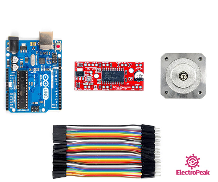
Hardware component
software Apps
Note
Note that you need a proper power supply (adapter, battery, etc.) to interface this motor with EasyDriver driver. The power supply is not listed above. Prepare one yourself.
Warning
When you want to choose a power supply, pay attention to the voltage and current passing through the stepper motor and its driver.
For example, you can use a 12V and 1A power supply.
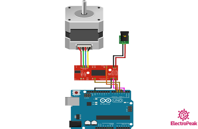
Interfacing BYGH403 Stepper Motor with Arduino
Step 1: Circuit
The following circuit shows how you should connect Arduino to BYGH403 motor. Connect wires accordingly.
Step 2: Code
Upload the following code to Arduino.
 /*
  BYGH403-1.65A-Stepper-Motor
  made on 21 Dec 2020
  by Amir Mohammad Shojaee @ Electropeak
  Home

*/

#define stp 2
#define dir 3
#define MS1 4
#define MS2 5

int x;

void setup() {
  pinMode(stp, OUTPUT);
  pinMode(dir, OUTPUT);
  pinMode(MS1, OUTPUT);
  pinMode(MS2, OUTPUT);

  digitalWrite(MS1,LOW);
  digitalWrite(MS2,LOW);
}

void loop() {
  digitalWrite(dir, HIGH);
  for(x= 0; x<1000; x++)
  {
    digitalWrite(stp,HIGH);
    delay(1);
    digitalWrite(stp,LOW);
    delay(1);
  }
  delay(1000);

  digitalWrite(dir, LOW);
  for(x= 0; x<1000; x++)
  {
    digitalWrite(stp,HIGH);
    delay(1);
    digitalWrite(stp,LOW);
    delay(1);
  }
  delay(1000);
}
In this program, 4 pins are used: STP, DIR, MS1 and MS2. We set MS1 and MS2 to LOW so that the stepper motor rotates in full step mode.
When the program runs, the stepper motor will rotate 5 times clockwise and 5 times counter-clockwise.
