Interfacing Heart Rate Pulse Sensor Module with Arduino
Written by
Mohammadreza Akbari
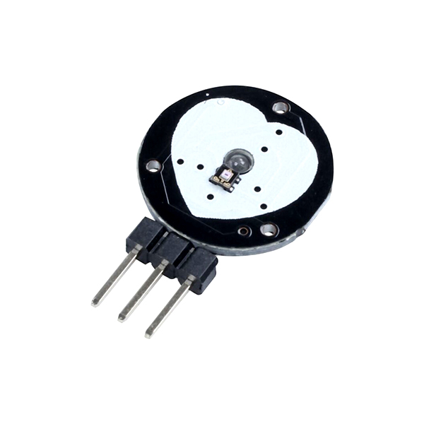
Heart Rate Pulse Sensor Features
Heart Rate Pulse Sensor can be used to measure the heart rate and some related parameters such as cardiac arrhythmia (i.e., abnormal heart rhythm). If you touch this sensor with any area of your skin that is closest to the arteries (such as the finger or earlobe), the sensor detects blood in the arteries. Each time the heart beats, blood is pumped through the arteries, and the sensor detects the flow of blood and increases the output voltage.
Note
This sensor has an analog output which is directly related to the amount of blood in the arteries and capillaries.
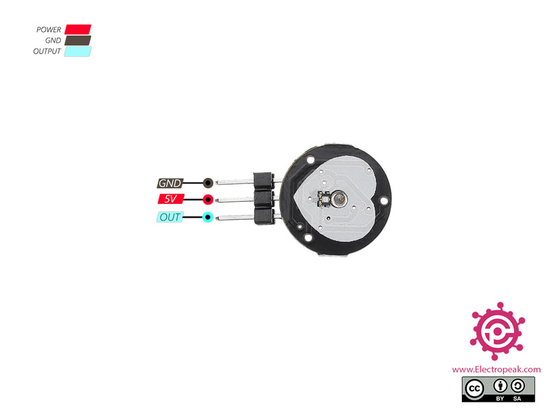
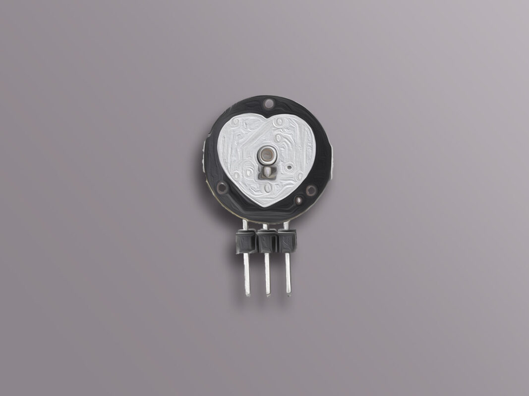
Heart Rate Pulse Sensor Pinout
This Module has 3 pins:
+: Module power supply – 5 V
–: Ground
S: Output
You can see the pinout of this module in the image below.
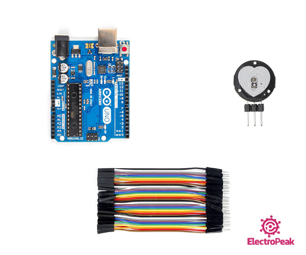
Required Materials
Hardware Components
Arduino UNO R3
×
1
Heart Rate Pulse Sensor
×
1
Male to female jumper wire
×
1
Software Apps
Arduino IDE
Interfacing Heart Rate Pulse Sensor with Arduino
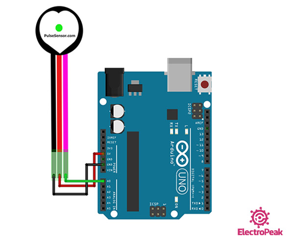
Step 1: Circuit
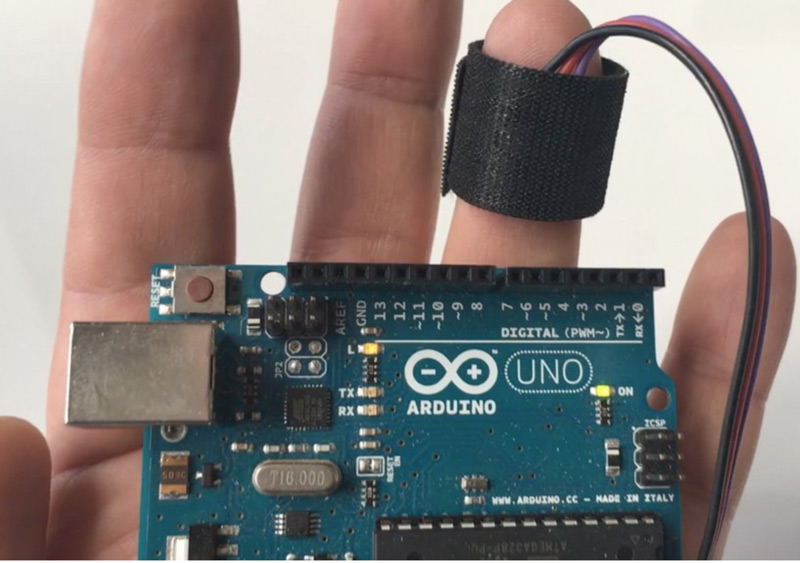
The following circuit shows how you should connect Arduino to this sensor. Connect wires accordingly.
Tip
Put the sensor on a black belt for better function.
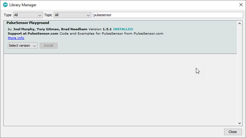
Step 2: Installing Library
Go to Library manager and install the heart rate sensor library.
Step 3: Code
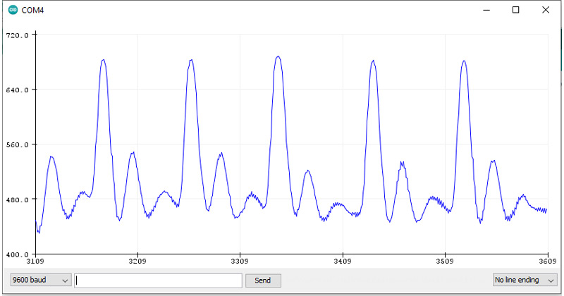
Upload the following code to Arduino. After that, open the Serial Plotter window.
Based on Library Example
*/
/* PulseSensor Starter Project and Signal Tester
The Best Way to Get Started With, or See the Raw Signal of, your PulseSensor.comâ„¢ & Arduino.
Here is a link to the tutorial
https://pulsesensor.com/pages/code-and-guide
WATCH ME (Tutorial Video):
-------------------------------------------------------------
1) This shows a live human Heartbeat Pulse.
2) Live visualization in Arduino's Cool "Serial Plotter".
3) Blink an LED on each Heartbeat.
4) This is the direct Pulse Sensor's Signal.
5) A great first-step in troubleshooting your circuit and connections.
6) "Human-readable" code that is newbie friendly."
*/
// Variables
int PulseSensorPurplePin = A0; // Pulse Sensor PURPLE WIRE connected to ANALOG PIN 0
int LED13 = 13; // The on-board Arduion LED
int Signal; // holds the incoming raw data. Signal value can range from 0-1024
int Threshold = 550; // Determine which Signal to "count as a beat", and which to ingore.
// The SetUp Function:
void setup() {
pinMode(LED13, OUTPUT); // pin that will blink to your heartbeat!
Serial.begin(9600); // Set's up Serial Communication at certain speed.
}
// The Main Loop Function
void loop() {
Signal = analogRead(PulseSensorPurplePin); // Read the PulseSensor's value.
// Assign this value to the "Signal" variable.
Serial.println(Signal); // Send the Signal value to Serial Plotter.
if (Signal > Threshold) { // If the signal is above "550", then "turn-on" Arduino's on-Board LED.
digitalWrite(LED13, HIGH);
} else {
digitalWrite(LED13, LOW); // Else, the sigal must be below "550", so "turn-off" this LED.
}
delay(10);
}