
Overview
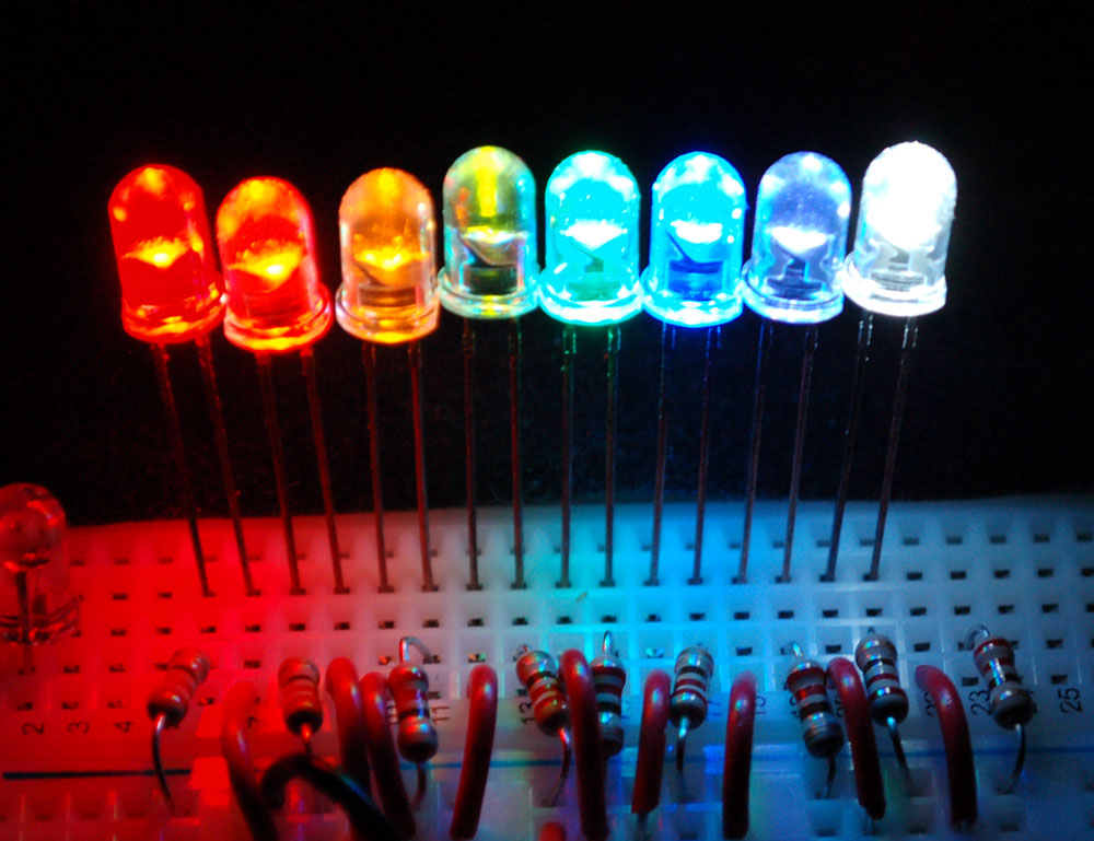
Which feature of RGB LEDs has made them an attractive and practical component in Electronics and Lighting Industry?
Answer: Their unique feature of regulating the ratio of the three primary colors (red, green, and blue) to generate a desired color with one LED. An RGB LED has a common pin as well as three pins for red, green, and blue colors. We can combine these primary colors to generate countless colors by controlling these pins with a PWM pulse signal. (The number of colors changes depending on the resolution of the generated PWM signal).
These components are controlled by microcontrollers and PWM drivers. Since every microcontroller has a limited number of pins and output current, various modules have been developed to increase PWM channels in order to control RGB LEDs. However, controlling each RGB LED separately has many issues and it will increase the cost sharply.
In some way, this issue has been resolved in the next generation of RGB LEDs. The WS1812 series of LEDs, which has an internal controller with the same name, is considered “evolved RGB LEDs.” And only one data line is used to communicate with these programmable controllers and change the color of LEDs. What’s more interesting is that a large number of these LEDs can be linked together and controlled by the same data line, thanks to the “cascade” and “addressing” features on these LEDs.
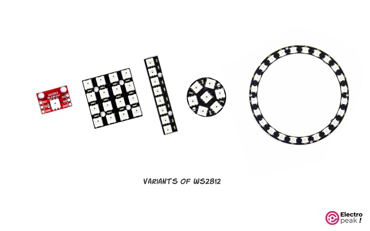
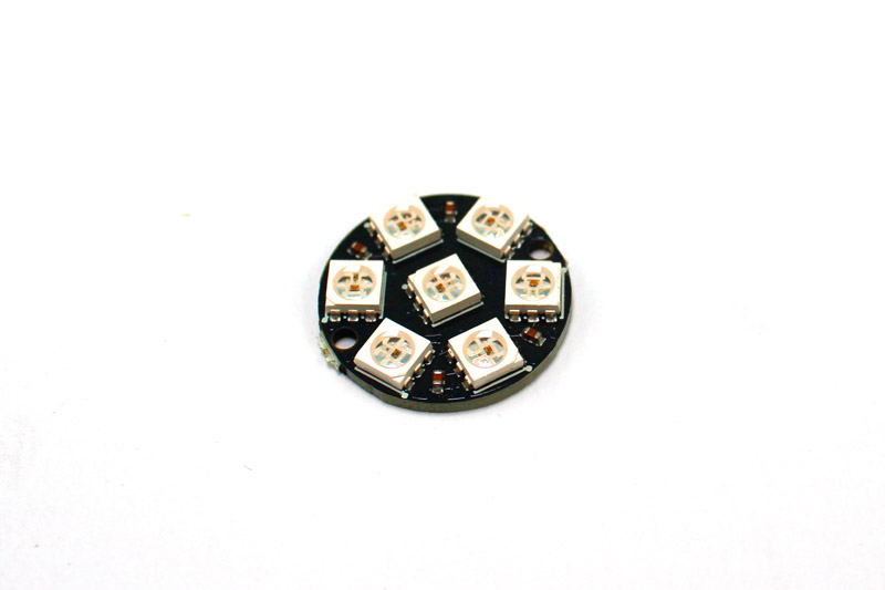
The market offers WS2812 series LEDs both individually and in modules in a variety of quantities and shapes, simplifying the use of this popular technology for various projects.
What Is NeoPixel?
To control each RGB LED, you need three digital pins of a microcontroller (or the development boards like Arduino). For example, if you want to control an RGB LED string containing 60 LEDs, in order to control the color of each LED separately, you need 180 digital pins! So you have to forget controlling each LED individually or use LEDs that are addressable.
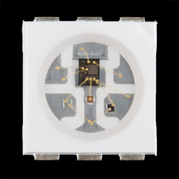
Addressable LEDs are a new generation of LEDs including a controller IC, in addition to RGB LEDs. This controller IC, usually WS2812, allows you to access multiple LEDs with a single digital pin by assigning an address to each LED and providing one wire communication. But unlike simple LEDs, these types of LEDs do not turn on only by applying voltage, they also require a microcontroller. NeoPixel is the Adafruit brand for addressable LEDs.
The ability to control each LED in an LED strip will create great visual effects in your projects. But it should be noted that in the very fast processes like POVs, the use of NeoPixels is not recommended. The other important advantage of the WS2812 LEDs (NeoPixels) is their lower price compared to other addressable LEDs. WS2812 LEDs are also available in the ring, strip, square and circular models and you can select the suitable model according to your project.
WS2812 LEDs are also chainable, so you can control multiple LEDs with only one command line and one power line.
WS2812 Datasheet And Features
- Input voltage: 5V (or 4 to 7V)
- LED package: 5050
- Current consumption of each LED in the maximum lighting mode: 60 mA
- Current consumption of each color: 20mA * duty cycle of that color
- Scan frequency: at least 400Hz
- Data transfer speed: 800Kbps
- Built-in electric reset circuit and power lost reset circuit
- Communication protocol: NZR single wire
For more information, check out the datasheet:
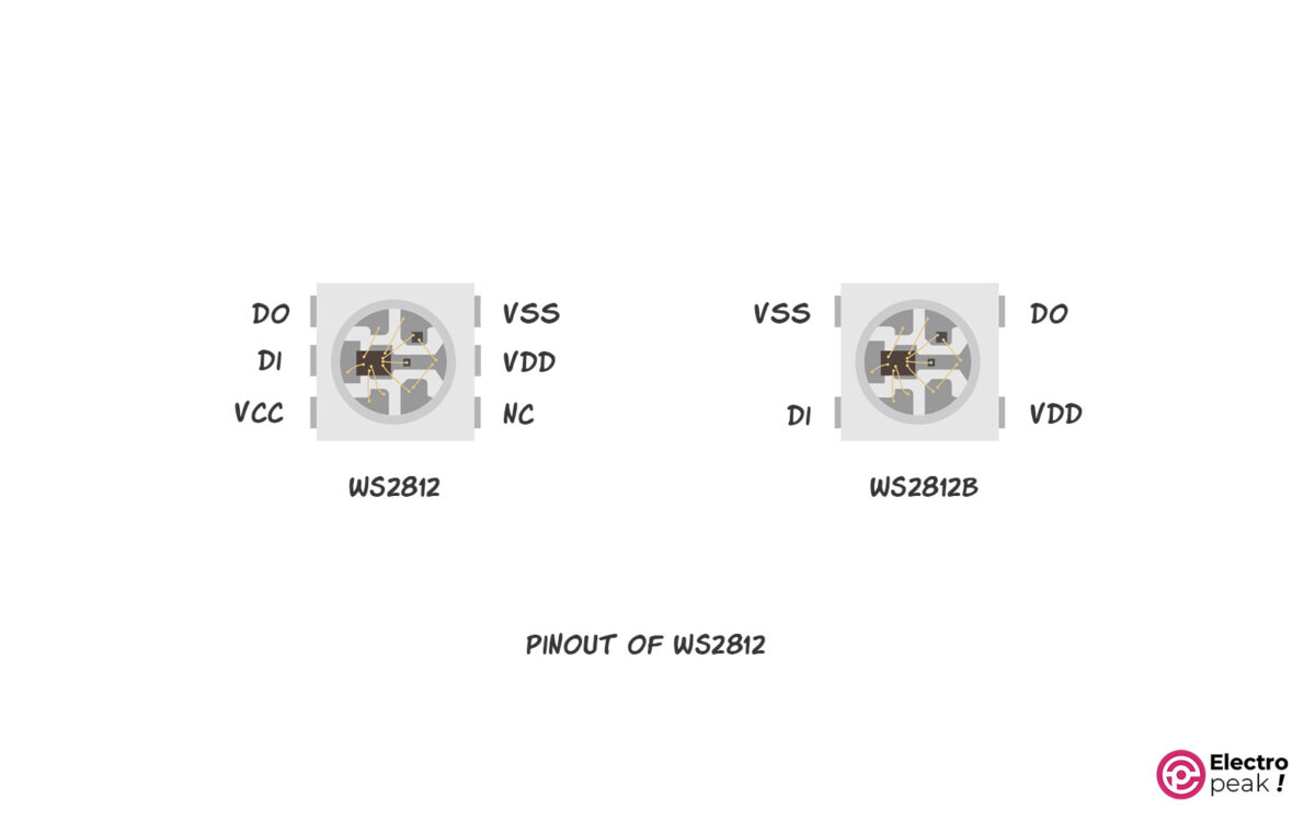
WS2812 VS. WS2812(B)
There are two common types of these LEDs—WS2812 and WS2812B. WS2812Bs are more popular. The only differences are the number and function of the pins.
In the WS2812 model, the power supply for the LED and the control circuit are separate, but these two pins are the same in WS2812Bs.
WS2812 Pinout
6-Pin Model:
- VSS: Ground
- VDD: LED power supply
- VCC: power supply of the control circuit
- NC: not connected anywhere!!
- DIN/IN/DI: data signal input (either from the microcontroller or from the previous blocks)
- DO/DOUT/OUT: data signal output (to connect to the next block)
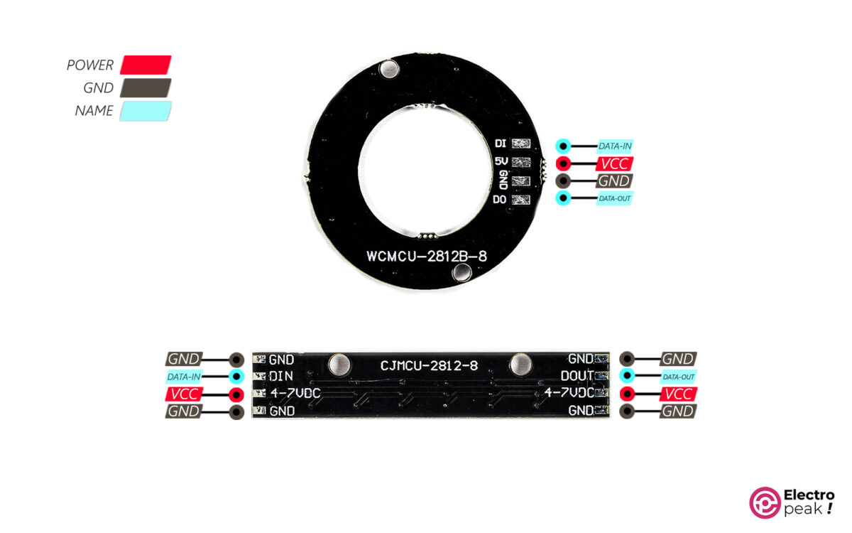
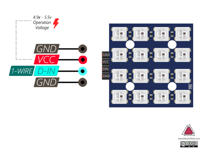
4-Pin Model:
- VCC/VDC: positive pin of the module power supply (5V in some modules. 4 to 7V is also suitable.)
- GND: Ground
- DIN/IN/DI: data signal input (either from the microcontroller or from the previous blocks)
- DO/DOUT/OUT: data signal output (to connect to the next block)
Required Materials
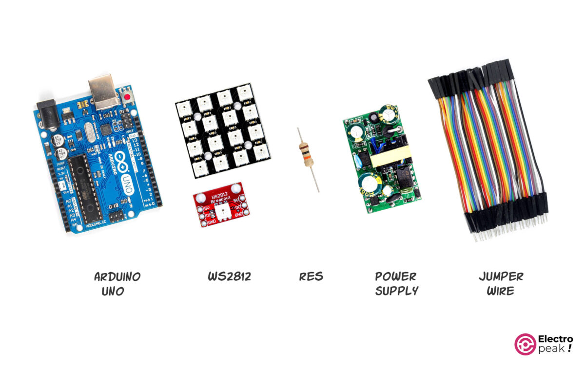
When buying WS2812 LEDs, choose any model that is best for your project; their interface process is the same.
Hardware Components
Software Apps
Interfacing WS2812 with Arduino
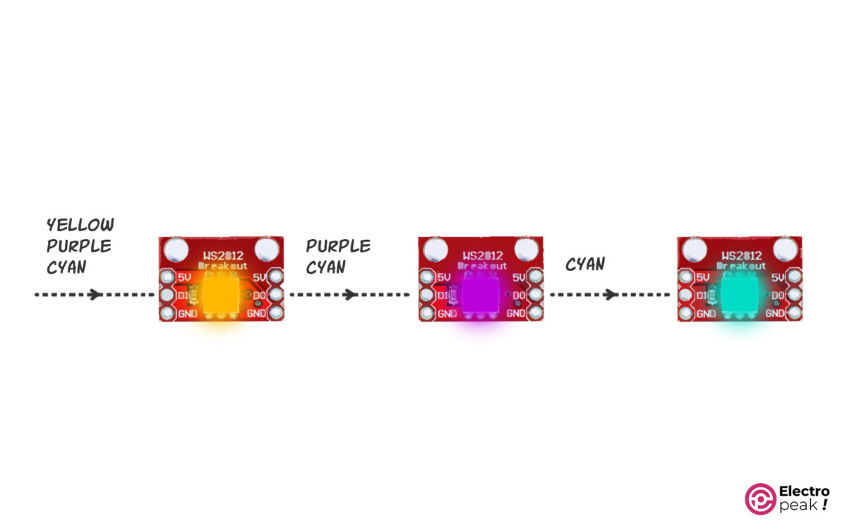
As mentioned, a large number of LEDs can be set up with only one data line, and the data is transferred from one block of LEDs to another.
How WS2812 Module Works with Arduino
The color data is transmitted sequentially by an Arduino digital pin. The first LED will be turned on according to the value of the first color. The remaining data is sent to the next LED by the Dout pin, and so on. The same applies when connecting multiple modules that have several LEDs. The last LED of the previous module transmits data to the first LED of the next module, and so on, up to the final pixel.
Use a Suitable Power Supply
Providing a suitable power supply is probably the first step for interfacing any system.
The suitable voltage for running these LEDs is 5V.
Each WS2812 LED can use up to 60mA of current at a time. The required current for the LEDs is equal to the number of LEDs multiplied by this value (60mA). For example, the minimum power supply current needed to run 16 LEDs is 960mA (16 x 60mA = 960mA).
So, a “5V 1A power supply” can run 16 of such LEDs.
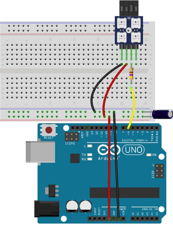
Wiring
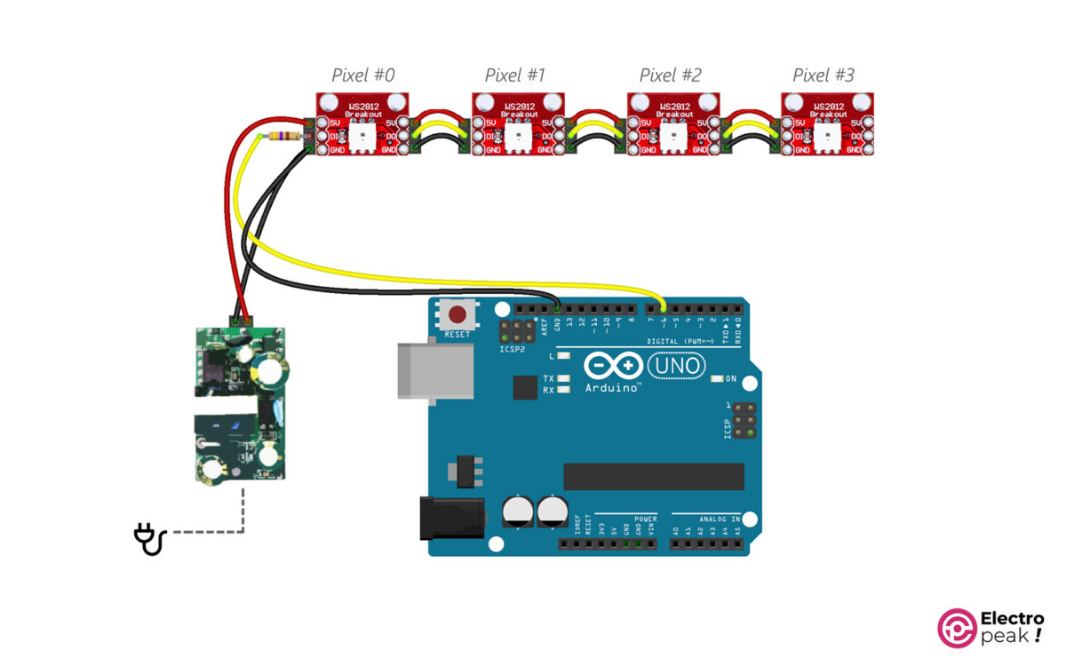
The data line should have a 300 to 500Ω resistor added to the beginning of it to prevent an unwanted current draw. This single resistor will be enough for all modules.
The data line in our project is connected to the Arduino digital pin # 6. You can use any other digital pin. Just remember to specify it in the code.
2- Don't forget to connect the Arduino power!! If connected to the computer, Arduino will draw its voltage from the computer; but if not, connect it to a suitable power supply. You can also use the 5V power supply by connecting its positive pin to the 5v pin of Arduino. And the circuit Gnd must always be the same.
3- You can connect a 1000 F electrolytic capacitor between the positive lines and the ground if you don't want to use a high-quality power supply with a minimum output voltage ripple.
Install The Neopixels Arduino Library
Upload the Code
To test the WS2812 LEDs, we can use the code below. It turns on every pixel one by one and then turns them off all at once. Copy and run the following code in Arduino.
// Electropeak . CafeRobot
// Ali Akbar Hosseini
// Adafruit NeoPixel library simple test

#include <Adafruit_NeoPixel.h>
#ifdef __AVR__
 #include <avr/power.h> // Required for 16 MHz Adafruit Trinket
#endif

// Which pin on the Arduino is connected to the NeoPixels?
#define PIN 6 // On Trinket or Gemma, suggest changing this to 1

// How many NeoPixels are attached to the Arduino?
#define NUMPIXELS 16 // Popular NeoPixel ring size

// When setting up the NeoPixel library, we tell it how many pixels,
// and which pin to use to send signals. Note that for older NeoPixel
// strips you might need to change the third parameter -- see the
// strandtest example for more information on possible values.
Adafruit_NeoPixel pixels(NUMPIXELS, PIN, NEO_GRB + NEO_KHZ800);

#define DELAYVAL 500 // Time (in milliseconds) to pause between pixels

void setup() {
 // These lines specifically support the Adafruit Trinket 5V 16 MHz.
 // Any other board, you can remove this part (but no harm leaving it):
#if defined(__AVR_ATtiny85__) && (F_CPU == 16000000)
 clock_prescale_set(clock_div_1);
#endif
 // END of Trinket-specific code.
 pixels.begin(); // INITIALIZE NeoPixel strip object (REQUIRED)
}

void loop() {
 pixels.clear(); // Set all pixel colors to 'off'

 // The first NeoPixel in a strand is #0, second is 1, all the way up
 // to the count of pixels minus one.
 delay(500);
 for(int i=0; i<NUMPIXELS; i++) { // For each pixel...

 // pixels.Color() takes RGB values, from 0,0,0 up to 255,255,255
 // Here we're using a moderately bright green color:
 pixels.setPixelColor(i, pixels.Color(150, 150, 0));
 pixels.show(); // Send the updated pixel colors to the hardware.

 delay(DELAYVAL); // Pause before next pass through loop
 }
}
A brief explanation of the code above:
With the following command, we determine the number of connected LEDs. For example, here, the number is 16.
#define NUMPIXELS 16
All LEDs will be turned off using the pixels.clear(); command.
In the first line of the following command, the color of pixel # i is defined by “pixels.Color(150, 150, 0).” And then, in the second line, these changes are applied.
pixels.setPixelColor(i, pixels.Color(150, 150, 0));
 pixels.show();
pixels.Color(R, G, B) receives red, green, and blue color values ranging from 0 to 255. For example, pixels.Color(255, 0, 0) will light a red color, but you will see a green color with pixels.Color(0, 255, 0). So we can produce 256*256*256 distinct colors with one single LED by combining these numbers. Interfacing Several WS2812 Modules with Arduino
There is no difference between connecting single LEDs or a few modules containing several LEDs. The last pixel of each module sends data to the first pixel of the next one, and so on, until the final pixel. It’s even possible to connect several modules with different numbers of pixels because Arduino sees them all as a series of pixels.
Wiring
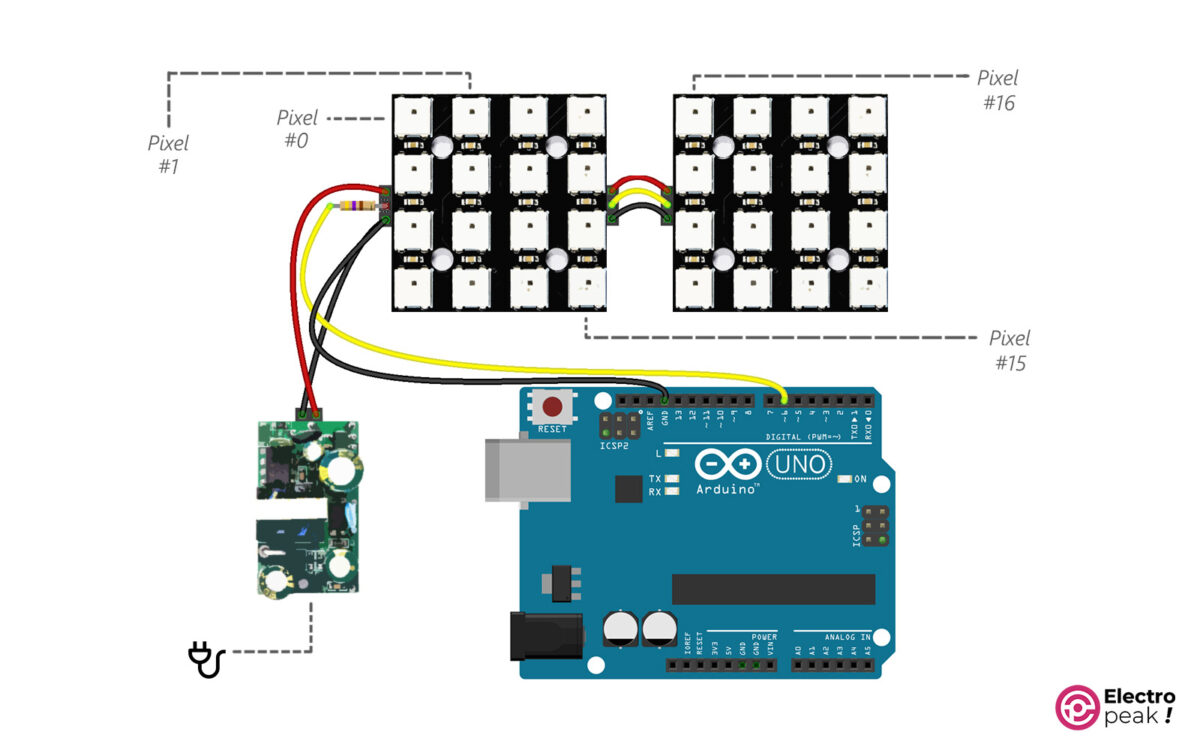
In the circuit above, like the previous one, the data wire (the yellow one) goes into the IN pin of the WS2812 module and then exits from the OUT pin, and then goes into the IN pin of the next module, and so on.
Here, we have 32 LEDs, so the required current goes up to 1920mA (32×60=1920mA). As a result, we need a power supply with a minimum output of 2A. (Note that “1920 mA” is for when all 32 LEDs are fully lit).
Code
After wiring the circuit, copy and run the following code in Arduino.
// Electropeak . CafeRobot
// Ali Akbar Hosseini
// Adafruit NeoPixel library RGBtest

#include <Adafruit_NeoPixel.h>
#ifdef __AVR__
 #include <avr/power.h> // Required for 16 MHz Adafruit Trinket
#endif

// Which pin on the Arduino is connected to the NeoPixels?
// On a Trinket or Gemma we suggest changing this to 1:
#define LED_PIN 6

// How many NeoPixels are attached to the Arduino?
#define LED_COUNT 32

// NeoPixel brightness, 0 (min) to 255 (max)
#define BRIGHTNESS 50 // Set BRIGHTNESS to about 1/5 (max = 255)

// Declare our NeoPixel strip object:
Adafruit_NeoPixel strip(LED_COUNT, LED_PIN, NEO_GRBW + NEO_KHZ800);
// Argument 1 = Number of pixels in NeoPixel strip
// Argument 2 = Arduino pin number (most are valid)
// Argument 3 = Pixel type flags, add together as needed:
// NEO_KHZ800 800 KHz bitstream (most NeoPixel products w/WS2812 LEDs)
// NEO_KHZ400 400 KHz (classic 'v1' (not v2) FLORA pixels, WS2811 drivers)
// NEO_GRB Pixels are wired for GRB bitstream (most NeoPixel products)
// NEO_RGB Pixels are wired for RGB bitstream (v1 FLORA pixels, not v2)
// NEO_RGBW Pixels are wired for RGBW bitstream (NeoPixel RGBW products)

void setup() {
 // These lines are specifically to support the Adafruit Trinket 5V 16 MHz.
 // Any other board, you can remove this part (but no harm leaving it):
#if defined(__AVR_ATtiny85__) && (F_CPU == 16000000)
 clock_prescale_set(clock_div_1);
#endif
 // END of Trinket-specific code.

 strip.begin(); // INITIALIZE NeoPixel strip object (REQUIRED)
 strip.show(); // Turn OFF all pixels ASAP
 strip.setBrightness(BRIGHTNESS);
}

void loop() {
 // Fill along the length of the strip in various colors...
 colorWipe(strip.Color(255, 0, 0) , 50); // Red
 colorWipe(strip.Color( 0, 255, 0) , 50); // Green
 colorWipe(strip.Color( 0, 0, 255) , 50); // Blue
 colorWipe(strip.Color( 0, 0, 0, 255), 50); // True white (not RGB white)

 whiteOverRainbow(75, 5);

 pulseWhite(5);

 rainbowFade2White(3, 3, 1);
}

// Fill strip pixels one after another with a color. Strip is NOT cleared
// first; anything there will be covered pixel by pixel. Pass in color
// (as a single 'packed' 32-bit value, which you can get by calling
// strip.Color(red, green, blue) as shown in the loop() function above),
// and a delay time (in milliseconds) between pixels.
void colorWipe(uint32_t color, int wait) {
 for(int i=0; i<strip.numPixels(); i++) { // For each pixel in strip...
 strip.setPixelColor(i, color); // Set pixel's color (in RAM)
 strip.show(); // Update strip to match
 delay(wait); // Pause for a moment
 }
}

void whiteOverRainbow(int whiteSpeed, int whiteLength) {

 if(whiteLength >= strip.numPixels()) whiteLength = strip.numPixels() - 1;

 int head = whiteLength - 1;
 int tail = 0;
 int loops = 3;
 int loopNum = 0;
 uint32_t lastTime = millis();
 uint32_t firstPixelHue = 0;

 for(;;) { // Repeat forever (or until a 'break' or 'return')
 for(int i=0; i<strip.numPixels(); i++) { // For each pixel in strip...
 if(((i >= tail) && (i <= head)) || // If between head & tail...
 ((tail > head) && ((i >= tail) || (i <= head)))) {
 strip.setPixelColor(i, strip.Color(0, 0, 0, 255)); // Set white
 } else { // else set rainbow
 int pixelHue = firstPixelHue + (i * 65536L / strip.numPixels());
 strip.setPixelColor(i, strip.gamma32(strip.ColorHSV(pixelHue)));
 }
 }

 strip.show(); // Update strip with new contents
 // There's no delay here, it just runs full-tilt until the timer and
 // counter combination below runs out.

 firstPixelHue += 40; // Advance just a little along the color wheel

 if((millis() - lastTime) > whiteSpeed) { // Time to update head/tail?
 if(++head >= strip.numPixels()) { // Advance head, wrap around
 head = 0;
 if(++loopNum >= loops) return;
 }
 if(++tail >= strip.numPixels()) { // Advance tail, wrap around
 tail = 0;
 }
 lastTime = millis(); // Save time of last movement
 }
 }
}

void pulseWhite(uint8_t wait) {
 for(int j=0; j<256; j++) { // Ramp up from 0 to 255
 // Fill entire strip with white at gamma-corrected brightness level 'j':
 strip.fill(strip.Color(0, 0, 0, strip.gamma8(j)));
 strip.show();
 delay(wait);
 }

 for(int j=255; j>=0; j--) { // Ramp down from 255 to 0
 strip.fill(strip.Color(0, 0, 0, strip.gamma8(j)));
 strip.show();
 delay(wait);
 }
}

void rainbowFade2White(int wait, int rainbowLoops, int whiteLoops) {
 int fadeVal=0, fadeMax=100;

 // Hue of first pixel runs 'rainbowLoops' complete loops through the color
 // wheel. Color wheel has a range of 65536 but it's OK if we roll over, so
 // just count from 0 to rainbowLoops*65536, using steps of 256 so we
 // advance around the wheel at a decent clip.
 for(uint32_t firstPixelHue = 0; firstPixelHue < rainbowLoops*65536;
 firstPixelHue += 256) {

 for(int i=0; i<strip.numPixels(); i++) { // For each pixel in strip...

 // Offset pixel hue by an amount to make one full revolution of the
 // color wheel (range of 65536) along the length of the strip
 // (strip.numPixels() steps):
 uint32_t pixelHue = firstPixelHue + (i * 65536L / strip.numPixels());

 // strip.ColorHSV() can take 1 or 3 arguments: a hue (0 to 65535) or
 // optionally add saturation and value (brightness) (each 0 to 255).
 // Here we're using just the three-argument variant, though the
 // second value (saturation) is a constant 255.
 strip.setPixelColor(i, strip.gamma32(strip.ColorHSV(pixelHue, 255,
 255 * fadeVal / fadeMax)));
 }

 strip.show();
 delay(wait);

 if(firstPixelHue < 65536) { // First loop,
 if(fadeVal < fadeMax) fadeVal++; // fade in
 } else if(firstPixelHue >= ((rainbowLoops-1) * 65536)) { // Last loop,
 if(fadeVal > 0) fadeVal--; // fade out
 } else {
 fadeVal = fadeMax; // Interim loop, make sure fade is at max
 }
 }

 for(int k=0; k<whiteLoops; k++) {
 for(int j=0; j<256; j++) { // Ramp up 0 to 255
 // Fill entire strip with white at gamma-corrected brightness level 'j':
 strip.fill(strip.Color(0, 0, 0, strip.gamma8(j)));
 strip.show();
 }
 delay(1000); // Pause 1 second
 for(int j=255; j>=0; j--) { // Ramp down 255 to 0
 strip.fill(strip.Color(0, 0, 0, strip.gamma8(j)));
 strip.show();
 }
 }

 delay(500);
}
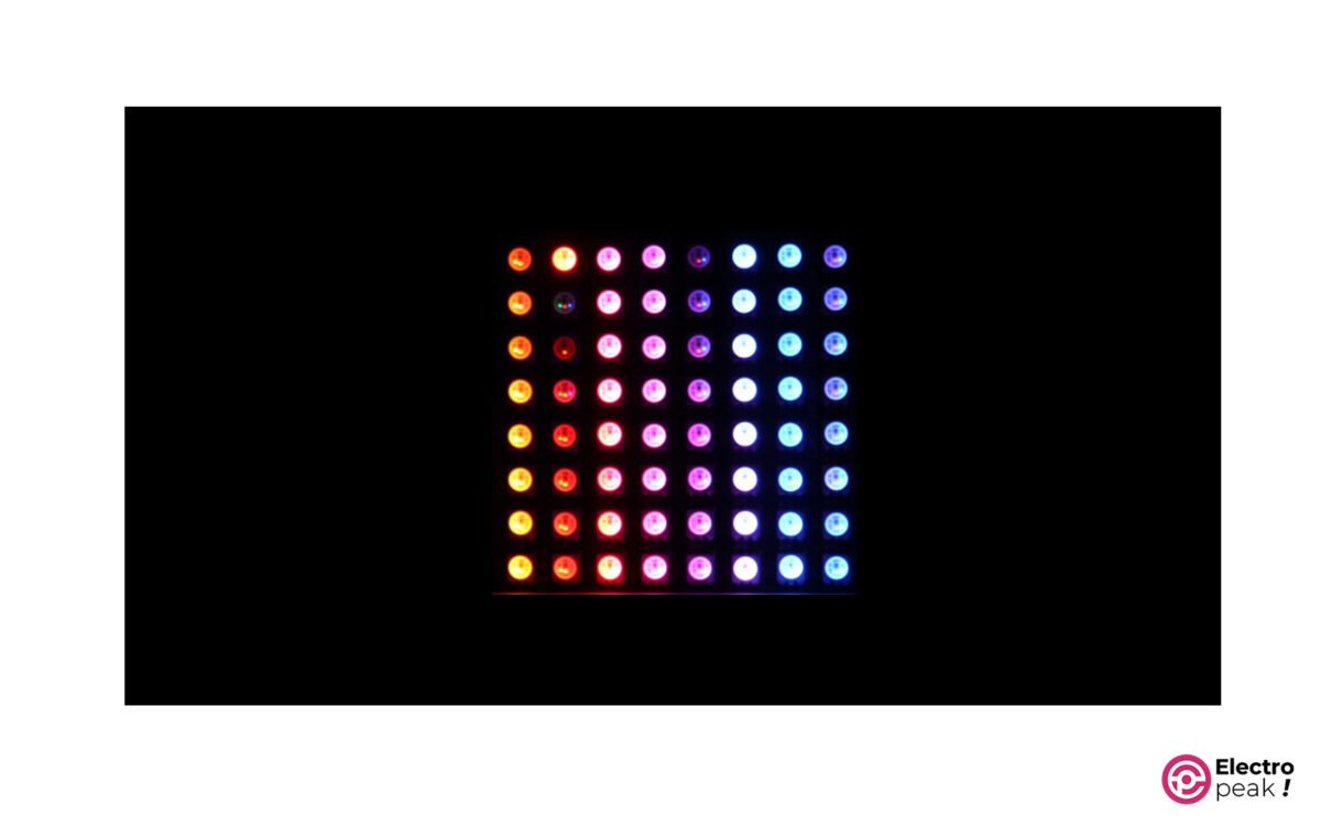
The code above generates various color scenarios.
The number of pixels (LEDs) is specified in the following line. As mentioned, 32 for us. It doesn’t matter if you use modules with different numbers of LEDs. Just remember to enter the total number of LEDs correctly in the line below to make sure that all LEDs will be tested.
#define LED_COUNT 32
The video below shows the outcome of the above code on a module with 16 LEDs.
Ex.1: Simple Interface of WS2812 NeoPixel with Arduino
Pinout
Circuit
Note
Note
Note
code
/*
  NeoPixel LEDs

  modified on 7 May 2019
  by Saeed Hosseini @ Electropeak
**This code is based on Adafruit NeoPixel library Example**
  Home

*/

#include <Adafruit_NeoPixel.h>
#ifdef __AVR__
#include <avr/power.h> // Required for 16 MHz Adafruit Trinket
#endif

#define PIN      6
#define NUMPIXELS 7


Adafruit_NeoPixel pixels(NUMPIXELS, PIN, NEO_GRB + NEO_KHZ800);

#define DELAYVAL 500 // Time (in milliseconds) to pause between pixels

void setup() {
  pixels.begin();
}

void loop() {
  pixels.clear();
  pixels.setBrightness(10);
  pixels.setPixelColor(0, pixels.Color(255, 255, 255));
  pixels.setPixelColor(1, pixels.Color(255, 0, 0));
  pixels.setPixelColor(2, pixels.Color(0, 255, 0));
  pixels.setPixelColor(3, pixels.Color(0, 0, 255));
  pixels.setPixelColor(4, pixels.Color(255, 0, 255));
  pixels.setPixelColor(5, pixels.Color(255, 255, 0));
  pixels.setPixelColor(6, pixels.Color(0, 255, 255));
  pixels.show();
}
Code Explanation
Adafruit_NeoPixel pixels(NUMPIXELS, PIN, NEO_GRB + NEO_KHZ800);pixels.begin();pixel.setBrightness(b);pixels.setPixelColor(Wich LED,Wich color(Red,Green,Blue));pixels.show();Ex.2: WS2812 Blinking Mode with Arduino
/*

  NeoPixel LEDs

  modified on 7 May 2019
  by Saeed Hosseini @ Electropeak
  Home

*/

#include <Adafruit_NeoPixel.h>
#ifdef __AVR__
#include <avr/power.h> // Required for 16 MHz Adafruit Trinket
#endif

#define PIN        6
#define NUMPIXELS 7


Adafruit_NeoPixel pixels(NUMPIXELS, PIN, NEO_GRB + NEO_KHZ800);

void NeoBlink(int num, int wait)
{
  for (int i = 0; i < num; i++)
  {
    pixels.setPixelColor(i, 35, 35, 35);
  }
  pixels.show();
  delay(wait);
  for (int j = 0; j < num; j++)
  {
    pixels.setPixelColor(j, 0, 255, 0);
  }
  pixels.show();
  delay(wait);
}

void setup()
{
  pixels.begin();
  pixels.setBrightness(50);
}

void loop()
{
  NeoBlink(7, 500);
}
Ex.3: WS2812 Fading Mode with Arduino
/*

  NeoPixel LEDs

  modified on 7 May 2019
  by Saeed Hosseini @ Electropeak
  Home

*/

#include <Adafruit_NeoPixel.h>
#ifdef __AVR__
#include <avr/power.h> // Required for 16 MHz Adafruit Trinket
#endif

#define PIN        6
#define NUMPIXELS 7


Adafruit_NeoPixel pixels(NUMPIXELS, PIN, NEO_GRB + NEO_KHZ800);

#define DELAYVAL 500 // Time (in milliseconds) to pause between pixels

void NeoFade(int FadeSpeed)
{
  int fspeed;
  for (int i = 0; i < NUMPIXELS; i++) { pixels.setPixelColor(i, 165, 242, 243); } for (int j = 255; j > 0; j=j-2)
  {
    pixels.setBrightness(j);
    pixels.show();
    delay(FadeSpeed);
  }
}

void setup() {
  pixels.begin();
}

void loop() {
  NeoFade(100);
}
Ex.4: WS2812 Random Mode with Arduino
/*

  NeoPixel LEDs
  modified on 7 May 2019
  by Saeed Hosseini @ Electropeak
  Home

*/

#include <Adafruit_NeoPixel.h>
#ifdef __AVR__
#include <avr/power.h> // Required for 16 MHz Adafruit Trinket
#endif

#define PIN        6
#define NUMPIXELS 7


Adafruit_NeoPixel pixels(NUMPIXELS, PIN, NEO_GRB + NEO_KHZ800);

#define DELAYVAL 500 // Time (in milliseconds) to pause between pixels

void setup() {
  pixels.begin();
}

void loop() {
  pixels.clear();
  pixels.setPixelColor(random(0, 7), random(0, 255), random(0, 255), random(0, 255));
  pixels.show();
  delay(500);
}
Ex.5: WS2812 rainbow mode with Arduino
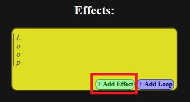
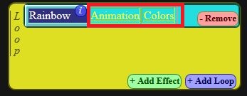
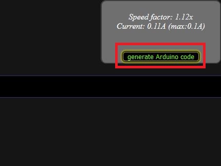
One of the most interesting tools on the web, to create effects on NeoPixels is the NeoPixel Effects Generator, which lets you specify the number of LEDs and Arduino pins, and after creating the effects and required settings, you can click on the generate Arduino code and copy the generated code to IDE. To do this, do the following steps:
- Click on Add Led Strip after entering the website.


/*
This code is generated by:
https://adrianotiger.github.io/NeoPixel-Effect-Generator/

*/
#include <Adafruit_NeoPixel.h>

class Strip
{
public:
  uint8_t   effect;
  uint8_t   effects;
  uint16_t  effStep;
  unsigned long effStart;
  Adafruit_NeoPixel strip;
  Strip(uint16_t leds, uint8_t pin, uint8_t toteffects) : strip(leds, pin, NEO_GRB + NEO_KHZ800) {
    effect = -1;
    effects = toteffects;
    Reset();
  }
  void Reset(){
    effStep = 0;
    effect = (effect + 1) % effects;
    effStart = millis();
  }
};

struct Loop
{
  uint8_t currentChild;
  uint8_t childs;
  bool timeBased;
  uint16_t cycles;
  uint16_t currentTime;
  Loop(uint8_t totchilds, bool timebased, uint16_t tottime) {currentTime=0;currentChild=0;childs=totchilds;timeBased=timebased;cycles=tottime;}
};

Strip strip_0(7, 6, 7 );
struct Loop strip0loop0(1, false, 1);

//[GLOBAL_VARIABLES]

void setup() {

  //Your setup here:

  strip_0.strip.begin();
}

void loop() {

  //Your code here:

  strips_loop();
}

void strips_loop() {
  if(strip0_loop0() & 0x01)
    strip_0.strip.show();
}

uint8_t strip0_loop0() {
  uint8_t ret = 0x00;
  switch(strip0loop0.currentChild) {
    case 0:
           ret = strip0_loop0_eff0();break;
  }
  if(ret & 0x02) {
    ret &= 0xfd;
    if(strip0loop0.currentChild + 1 >= strip0loop0.childs) {
      strip0loop0.currentChild = 0;
      if(++strip0loop0.currentTime >= strip0loop0.cycles) {strip0loop0.currentTime = 0; ret |= 0x02;}
    }
    else {
      strip0loop0.currentChild++;
    }
  };
  return ret;
}

uint8_t strip0_loop0_eff0() {
    // Strip ID: 0 - Effect: Rainbow - LEDS: 7
    // Steps: 8 - Delay: 87
    // Colors: 7 (255.0.0, 0.255.0, 0.0.255, 255.157.0, 255.0.255, 0.255.255, 255.255.255, )
    // Options: toLeft=true,
  if(millis() - strip_0.effStart < 87 * (strip_0.effStep)) return 0x00;
  float factor1, factor2;
  uint16_t ind;
  for(uint16_t j=0;j<7;j++) { ind = strip_0.effStep + j * 1.1428571428571428; switch((int)((ind % 8) / 1.1428571428571428)) { case 0: factor1 = 1.0 - ((float)(ind % 8 - 0 * 1.1428571428571428) / 1.1428571428571428); factor2 = (float)((int)(ind - 0) % 8) / 1.1428571428571428; strip_0.strip.setPixelColor(j, 255 * factor1 + 0 * factor2, 0 * factor1 + 255 * factor2, 0 * factor1 + 0 * factor2); break; case 1: factor1 = 1.0 - ((float)(ind % 8 - 1 * 1.1428571428571428) / 1.1428571428571428); factor2 = (float)((int)(ind - 1.1428571428571428) % 8) / 1.1428571428571428; strip_0.strip.setPixelColor(j, 0 * factor1 + 0 * factor2, 255 * factor1 + 0 * factor2, 0 * factor1 + 255 * factor2); break; case 2: factor1 = 1.0 - ((float)(ind % 8 - 2 * 1.1428571428571428) / 1.1428571428571428); factor2 = (float)((int)(ind - 2.2857142857142856) % 8) / 1.1428571428571428; strip_0.strip.setPixelColor(j, 0 * factor1 + 255 * factor2, 0 * factor1 + 157 * factor2, 255 * factor1 + 0 * factor2); break; case 3: factor1 = 1.0 - ((float)(ind % 8 - 3 * 1.1428571428571428) / 1.1428571428571428); factor2 = (float)((int)(ind - 3.4285714285714284) % 8) / 1.1428571428571428; strip_0.strip.setPixelColor(j, 255 * factor1 + 255 * factor2, 157 * factor1 + 0 * factor2, 0 * factor1 + 255 * factor2); break; case 4: factor1 = 1.0 - ((float)(ind % 8 - 4 * 1.1428571428571428) / 1.1428571428571428); factor2 = (float)((int)(ind - 4.571428571428571) % 8) / 1.1428571428571428; strip_0.strip.setPixelColor(j, 255 * factor1 + 0 * factor2, 0 * factor1 + 255 * factor2, 255 * factor1 + 255 * factor2); break; case 5: factor1 = 1.0 - ((float)(ind % 8 - 5 * 1.1428571428571428) / 1.1428571428571428); factor2 = (float)((int)(ind - 5.7142857142857135) % 8) / 1.1428571428571428; strip_0.strip.setPixelColor(j, 0 * factor1 + 255 * factor2, 255 * factor1 + 255 * factor2, 255 * factor1 + 255 * factor2); break; case 6: factor1 = 1.0 - ((float)(ind % 8 - 6 * 1.1428571428571428) / 1.1428571428571428); factor2 = (float)((int)(ind - 6.857142857142857) % 8) / 1.1428571428571428; strip_0.strip.setPixelColor(j, 255 * factor1 + 255 * factor2, 255 * factor1 + 0 * factor2, 255 * factor1 + 0 * factor2); break; } } if(strip_0.effStep >= 8) {strip_0.Reset(); return 0x03; }
  else strip_0.effStep++;
  return 0x01;
}
What’s Next?
- Test the other effects on your WS2812 LED.
- Try to control your WS2812 NeoPixel wirelessly. (WiFi, Bluetooth, …)

Comments (2)
Hi I’ve just purchased a SEEED XAIO RP2040 which has an onboard Neopixel LED. I generated a sequence in Arduino from your LED Strip Effects Generator but I cannot get the onboard NeoPixel to work. I know the Neopixel does function because I have tried it with other code examples in Ardiuno. It seems strange because I can simulate the same code on an Arduino Uno in Tinker cad. As far as I can tell the data in-pin for the NeoPixel is connected to Pin 12 on the XAIO but I do not see any action.
Any help would be appreciated.
Many thanks
Ian
Hi.dear
can you share your c code that you used?
I think you should change some define pins in c code