Overview
In this tutorial, you will learn how to create a navigation system by GSM module and Arduino instead of using GPS. At the end
What you will learn
- You will learn more about GSM modules and how to use it with Arduino.
- You can make a navigation system by GSM.
About Navigation
In navigation system, a radio station regularly sends signals around. These signals include the exact coordinates of that station. It does not matter whether the station is fixed, such as the Airport Control Tower, or movable, such as a satellite. The important thing is that the coordinates of the station itself should be known at any moment.
In this project, we want to make a navigation system without GPS module. Using GSM signals from your phone or other mobile devices is one way of finding location or tracking devices. When a GSM system is connected to a network, you will receive some information about the location of your device. We choose one of the GSM/GPRS SIMCOM modules to connect them to the network and an Arduino board to receive data and monitor the location of the device. Let’s do it.
Required Materials
Hardware Components
Software Apps
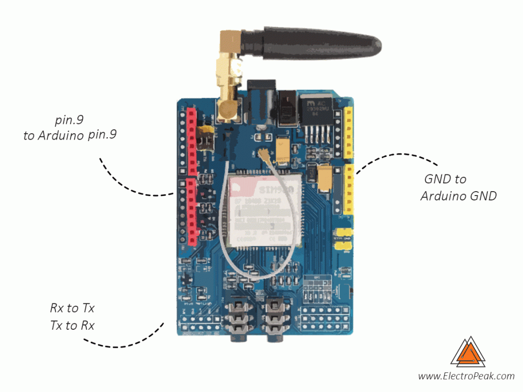
Circuit
Code
First, you must add the library. Download the Zip file, and add the file to Arduino IDE. Go to Sketch tab, Include library and Add ZIP Library. If it is the first time you are using an Arduino board, just follow these steps:
- Go to www.arduino.cc/en/Main/Software and download the Arduino software compatible to your OS. Install the IDE software as instructed.
- Run the Arduino IDE and clear the text editor and copy the following code in the text editor.
- Choose the board in tools and boards, select your Arduino Board.
- Connect the Arduino to your PC and set the COM port in tools and port.
- Press the Upload (Arrow sign) button.
- You are all set!
- Necessary Files and Downloads:
#include "SIM900.h"
#include "SoftwareSerial.h"
//#include "inetGSM.h"
//#include "sms.h"
//#include "call.h"

//To change pins for Software Serial, use the two lines in GSM.cpp.

//GSM Shield for Arduino
//this code is based on the example of Arduino Labs.

//Simple sketch to communicate with SIM900 through AT commands.

//InetGSM inet;
//CallGSM call;
//SMSGSM sms;

int numdata;
char inSerial[40];
int i=0;


void setup()
{
     //Serial connection.
     Serial.begin(9600);
     Serial.println("GSM Shield testing.");
     //Start configuration of shield with baudrate.
     //For http uses is raccomanded to use 4800 or slower.
     if (gsm.begin(9600))
          Serial.println("\nstatus=READY");
     else Serial.println("\nstatus=IDLE");
};

void loop()
{
     //Read for new byte on serial hardware,
     //and write them on NewSoftSerial.
     serialhwread();
     //Read for new byte on NewSoftSerial.
     serialswread();
};

void serialhwread()
{
     i=0;
     if (Serial.available() > 0) {
          while (Serial.available() > 0) {
               inSerial[i]=(Serial.read());
               delay(10);
               i++;
          }

          inSerial[i]='\0';
          if(!strcmp(inSerial,"/END")) {
               Serial.println("_");
               inSerial[0]=0x1a;
               inSerial[1]='\0';
               gsm.SimpleWriteln(inSerial);
          }
          //Send a saved AT command using serial port.
          if(!strcmp(inSerial,"TEST")) {
               Serial.println("SIGNAL QUALITY");
               gsm.SimpleWriteln("AT+CSQ");
          } else {
               Serial.println(inSerial);
               gsm.SimpleWriteln(inSerial);
          }
          inSerial[0]='\0';
     }
}

void serialswread()
{
     gsm.SimpleRead();
}
It’s simple to communicate with SIM900 through AT commands.
AT commands are commands for controlling modems. AT commands are actually derived from Hayes Command. All commands AT commands start with AT.
Be careful that AT is a prefix that receives a syntax and is not a command name. For example, one of the CMC + CMCAM commands is called AT + CMGS. There is another command called D that is sent to the modem as ATD.
Many GSM, GPRS, Bluetooth, and some other modules use AT commands for communication with computers and microcontrollers.
You can download all AT commands from Here.
Necessary Files and Downloads:
Now, to receive information about location, we need to use some special AT commands in order. After connecting to network, use these commands to prepare your modem to get the location data.
AT+CGATT =1 It’s for attaching GPRS. Probably, it’s on 1 by default.
AT+SAPBR =3,1,"CONTYPE","GPRS"
AT+SAPBR =3,1,"APN","RCMNET"
AT+SAPBR=1,1
AT+SAPBR=2,1
It’s bearer setting for applications based on IP
AT+CIPGSMLOC=1,1Finally, this command gets location, time and date. Note that for searching the location in google map, you must change (x,y) coordinates order to (y,x).
Look at the GIF for more details.
What’s Next?
- Try to use other modules with Arduino instead of GPS


Comments (2)
Dear Mrs Saeed Olfat,
Did this project work with you?
It’s not working with me at all. It gave me the following results in software serial:
====================
GSM Shield testing.
Trying to force the baud-rate to 9600
1200
2400
4800
9600
19200
38400
57600
115200
ERROR: SIM900 doesn’t answer. Check power and serial pins in GSM.cpp
status=IDLE
====================
Can you help me to overcome this issue?
Hi dear friend,
Yes, the code has worked well, and the results are also provided at the end of the article in a GIF file. If you’re getting an error like this, try setting up the gsm module and the Serial with a different baud rate, i.e. change the lines “Serial.begin(9600);” and “if (gsm.begin(9600))” to “Serial.begin(115200);” and “if (gsm.begin(115200))”, or any other baud rate. Hope that works for you.